
Novel mounting structure of rubber spring of vibration screen and method for replacing rubber spring

A rubber spring and installation structure technology, applied in the direction of low internal friction spring, spring/shock absorber, chemical instrument and method, etc., can solve the problems of noise, rubber spring can not be stretched, etc., to reduce noise, disassemble and replace quickly Convenience and easy replacement effect

Active Publication Date: 2016-04-20
CHINA UNIV OF MINING & TECH
View PDF5 Cites 4 Cited by
  • Summary
  • Abstract
  • Description
  • Claims
  • Application Information

AI Technical Summary

Problems solved by technology

In order to overcome the difficulty of spring replacement, some technicians have improved the installation structure of the rubber spring of the vibrating screen. The rubber spring is installed on the side of the screen box, and the lower support plate and the screen box are connected by bolts. However, in this improved technology, there are There are serious problems, such as during the operation of the vibrating screen, there are serious impacts, which generate a lot of noise, and the rubber spring can only be compressed but not stretched. The new spring cannot automatically deform during the replacement process. Does not fit smoothly between the screen boxes, so the practicality of this invention is questionable

Method used


Image

  • Novel mounting structure of rubber spring of vibration screen and method for replacing rubber spring
  • Novel mounting structure of rubber spring of vibration screen and method for replacing rubber spring
  • Novel mounting structure of rubber spring of vibration screen and method for replacing rubber spring

Examples


Embodiment 1

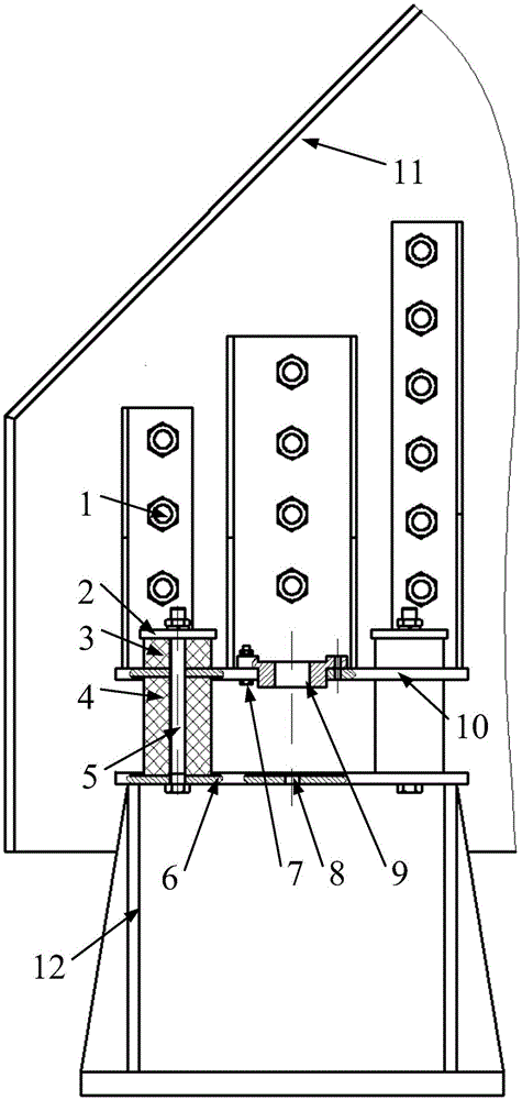
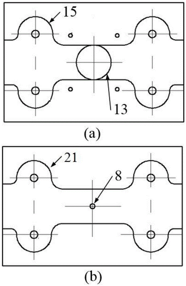
[0036] as attached figure 1 As shown, the new installation structure of the rubber spring of the vibrating screen includes a screen box 11, an installation base 12, an upper support plate 10, a lower support plate 6, replacement accessories and at least two sets of damping mechanisms; the upper support plate 11 is fixed on the screen by bolts 1 On the box 11, the lower support plate 6 is fixed on the installation base 12; the upper support plate 10 and the lower support plate 6 are connected by a damping mechanism, so that the screen box 11 can vibrate relative to the installation base 12; the vibration damping mechanism includes The first high-strength bolt 5, the main rubber spring 4 pressed between the upper support plate 10 and the lower support plate 6, the auxiliary rubber spring 3 placed above the upper support plate 10 and the pressing plate 2 placed on the upper end of the auxiliary rubber spring 3, the first The high-strength bolt 5 passes through the pressing plate 2,...

Embodiment 2

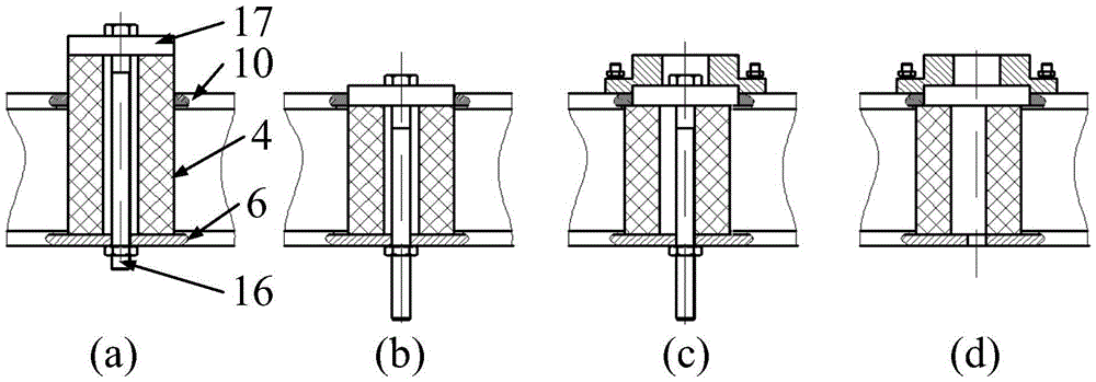
[0049] as attached Figure 4 As shown, the new installation structure of the rubber spring of the vibrating screen includes a screen box 11, an installation base 12, an upper support plate 10, a lower support plate 6, replacement accessories and at least two sets of damping mechanisms; the upper support plate 11 is fixed on the screen by bolts 1 On the box 11, the lower support plate 6 is fixed on the installation base 12; the upper support plate 10 and the lower support plate 6 are connected by a damping mechanism, so that the screen box 11 can vibrate relative to the installation base 12; the vibration damping mechanism includes The first high-strength bolt 5, the main rubber spring 4 pressed between the upper support plate 10 and the lower support plate 6, the auxiliary rubber spring 3 placed above the upper support plate 10 and the pressing plate 2 placed on the upper end of the auxiliary rubber spring 3, the first High-strength bolts 5 pass through the pressure plate 2, a...


PUM


Abstract

The invention discloses a novel mounting structure of a rubber spring of a vibration screen and a method for replacing the rubber spring. The novel mounting structure has the characteristics of variable stiffness and easy replacement. The structure mainly comprises an upper supporting plate, a lower supporting plate, main rubber springs, secondary rubber springs, pressing plates and first high-strength bolts, wherein the upper supporting plate is fixed to a screen box; the main rubber springs are positioned between the upper supporting plate and the lower supporting plate; the secondary rubber springs are positioned above the upper supporting plate and corresponding to the main rubber springs, and the pressing plates are positioned above the secondary rubber springs; the pressing plates, the secondary rubber springs, the main rubber springs, the upper supporting plate and the lower supporting plate are integrally connected through the first high-strength bolts. The novel mounting structure is reasonable, and convenient to dismount and replace, facilitates equipment repair, and can prolong the service life and improve the usage efficiency of equipment; meanwhile, the supporting stiffness of the screen box can be adjusted by changing the stiffness of the secondary rubber springs, so as to meet the amplitude requirements of different working conditions.

Description

technical field [0001] The invention relates to a vibrating screen, in particular to a new rubber spring installation structure of a vibrating screen and a method for replacing the rubber spring, which can realize variable stiffness function and simple spring replacement. Background technique [0002] Vibrating screen is a kind of mechanical equipment widely used in various industries such as mining, oil extraction, agriculture, construction, etc. It can realize functions such as screening, dehydration, and de-intermediation. The screen box of the vibrating screen and the installation base are connected by a damping spring. Commonly used damping springs include metal springs, rubber springs, and composite springs. Due to the low cost of rubber springs, good vibration damping effect, and good cold resistance, air tightness, waterproof, electrical insulation and other advantages, rubber springs have become the first choice for vibration damping springs in vibrating screen equi...

Claims


Application Information

Patent Timeline
Patent Type & Authority Applications(China)
IPC IPC(8): B07B1/46B07B1/28F16F1/36
CPCB07B1/28B07B1/46F16F1/36
Inventor 杨建华刘晓乐刘后广王文博程刚
Owner CHINA UNIV OF MINING & TECH
Learn More