Laminating device

A technology of laminating device and mounting plate, applied in the direction of building and building structure, can solve the problem of lateral vibration of vibration source, and achieve the effect of single vibration direction, wide applicability, and guaranteeing quality of lamination

Inactive Publication Date: 2017-06-27
TIANJIN BIBO TECH DEV CO LTD
View PDF0 Cites 0 Cited by
  • Summary
  • Abstract
  • Description
  • Claims
  • Application Information

AI Technical Summary

Problems solved by technology

[0003] The present invention provides a bonding device to solve the problem of lateral vibration of the vibration source existing in the current tile laying machine in the above-mentioned background technology

Method used


Image

  • Laminating device

Examples


Embodiment Construction

[0015] The technical solutions of the present invention will be clearly and completely described below in conjunction with the accompanying drawings. Apparently, the described embodiments are some of the embodiments of the present invention, but not all of them. Based on the embodiments of the present invention, all other embodiments obtained by persons of ordinary skill in the art without making creative efforts belong to the protection scope of the present invention.

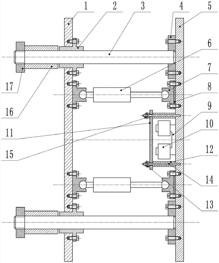
[0016] Specific examples of the present invention are attached figure 1 As shown, a bonding device includes: 1 fixed plate, 2 linear guide bushes, 3 guide shafts, 4 guide shaft connecting blocks, 5 tile fixture mounting plates, 6 linear actuators, 7 actuator supports, 8 rubber gasket, 9 vibrating iron core, 10 coil, 11 vibrating iron, 12 front rubber column, 13 rear rubber column, 14 vibrating iron fixed shaft, 15 natural frequency adjusting nut, 16 limit guide sleeve, 17 limit nut , the device is installed o...


PUM


Abstract

The invention belongs to the technical field of mechanical equipment, and in particular relates to a laminating device, which includes a fixed plate, a linear guide sleeve, a guide shaft, a guide shaft connection block, a tile fixture mounting plate, a linear actuator, and an actuator support. Rubber gasket, vibrating iron core, coil, vibrating iron, front rubber column, rear rubber column, vibrating iron fixed shaft, natural frequency adjusting nut, limit guide sleeve, limit nut. The vibration direction of the present invention is only the normal direction of the tiles, so when the tiles are closely attached, the vibration will not affect the adjacent tiles due to lateral vibration, and the vibration intensity can be changed by adjusting the current frequency on the coil and the natural frequency adjustment nut. To adapt to different tile sizes, plaster volume. It expands the use range of tile laying equipment, improves the quality of tile laying, and has good versatility and adaptability.

Description

technical field [0001] The invention belongs to the technical field of mechanical equipment, and in particular relates to a bonding device. Background technique [0002] The way of laying tiles by hand has the shortcomings of uneven tile gaps, poor flatness, low laying efficiency, and high labor intensity. Especially for large-sized tiles, manual laying is more difficult, and the average daily laying amount per capita is low. Therefore, the automation and mechanization of floor and wall tile laying has become an urgent and important issue. At present, there are many designs and applications of tile laying machines. Considering the insufficient diffusivity of the plaster and the short initial setting time of the solidification characteristics, many tile laying machines in the prior art have adopted the method of vibrating laying and pasting. , through vibration to speed up the uniform spreading of plaster. However, in the prior art, the vibration direction of the vibration ...

Claims


Application Information

Patent Timeline
IPC IPC(8): E04F21/18E04F21/22
CPCE04F21/18E04F21/22
Inventor 杨晓曼张俊兰赵玥起
Owner TIANJIN BIBO TECH DEV CO LTD
Why Eureka
Try Eureka