Variable-rigidity radial permanent magnet bearing

A permanent magnet bearing and variable stiffness technology, which is applied in the field of bearings to achieve the effect of reliable structure and improved system safety.

Active Publication Date: 2021-01-05
JIANGSU UNIV OF TECH
View PDF6 Cites 0 Cited by
  • Summary
  • Abstract
  • Description
  • Claims
  • Application Information

AI Technical Summary

Problems solved by technology

[0004] Aiming at the problem of commonly used supporting bearings in existing shaft systems, the present invention proposes a radial permanent magnetic bearing with variable stiffness, which includes: the outer ring of the permanent magnetic bearing, which is an integral ring and radially magnetized; the inner permanent magnetic bearing The magnetic ring block, the inner permanent magnetic ring block is radially magnetized, and the radial magnetization direction is opposite to the magnetization direction of the outer ring of the permanent magnetic bearing; the inner permanent magnetic ring support seat; the isolation ring section, the inner permanent magnet The ring blocks of the magnetic ring are evenly spaced on the inner permanent magnet ring support seat; the elastic ring arranges the inner permanent magnet ring support seat according to a ring rule, and can move freely in the radial direction; the variable stiffness radial permanent The magnetic bearing also includes: a conical block; a rolling bearing; a base; a shaft; a fixed hinge; a pendulum; Square shaft connection; elastic small shaft, the lower end of the elastic small shaft is connected to the base, and the upper end of the elastic small shaft is fixed on the equipment casing

Method used


Image

  • Variable-rigidity radial permanent magnet bearing
  • Variable-rigidity radial permanent magnet bearing
  • Variable-rigidity radial permanent magnet bearing

Examples


Embodiment Construction

[0018] In order to understand the characteristics and technical content of the present invention in more detail, the implementation of the present invention will be described in detail below in conjunction with the accompanying drawings. The attached drawings are only for reference and description, and are not intended to limit the present invention.

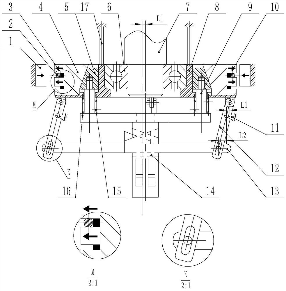
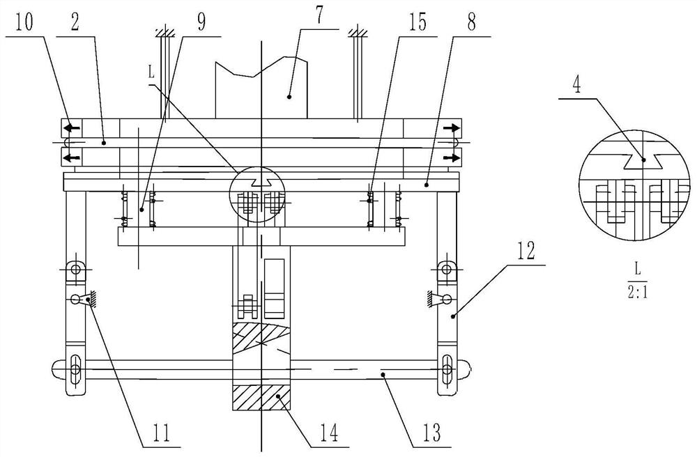
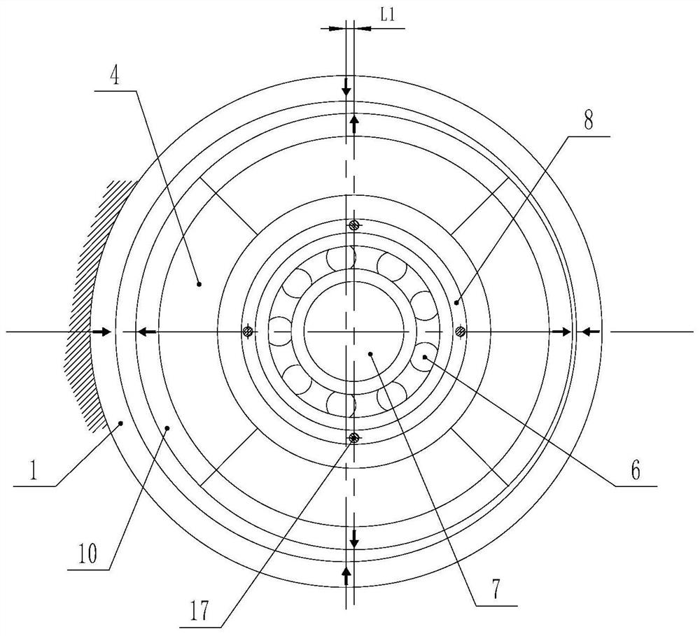
[0019] The invention provides a variable stiffness radial permanent magnetic bearing, such as Figure 1-Figure 3 as shown, figure 1 A schematic diagram of a variable stiffness radial permanent magnetic bearing provided by an embodiment of the present invention; figure 2 for figure 1 Schematic diagram of the left view of the view; image 3 for figure 1 A schematic top view of the view. The variable stiffness radial permanent magnetic bearing comprises: the outer ring 1 of the permanent magnetic bearing, the outer ring 1 of the permanent magnetic bearing is an integral ring, and is radially magnetized; the inner permanent mag...


PUM


Abstract

The invention provides a variable-rigidity radial permanent magnet bearing. The variable-rigidity radial permanent magnet bearing comprises a permanent magnet bearing outer ring which is an integral ring and is magnetized in the radial direction, inner permanent magnet ring blocks which are magnetized in the radial direction opposite to the magnetizing direction of the permanent magnet bearing outer ring, inner permanent magnet ring supporting seats, isolation ring sections for uniformly isolating the inner permanent magnet ring blocks on the inner permanent magnet ring supporting seats, elastic rings for arranging the inner permanent magnet ring supporting seats according to an annular rule and capable of freely moving along the radial direction, a conical block, a rolling bearing, a base, a shaft, a fixing hinge, a swing rod, a beveled swing rod, a square shaft, a supporting plate for connecting the conical block, the shaft and the square shaft, and a small elastic shaft with the lower end connected with the base and the upper end fixed to an equipment shell.

Description

technical field [0001] The invention relates to the technical field of bearings, in particular to a variable stiffness radial permanent magnetic bearing. Background technique [0002] In high-speed rotating machines such as centrifuges, turbines, and energy storage flywheels, in order to improve efficiency, they often work in a supercritical state, that is, the operating speed of the shafting is higher than the low-order critical speed (resonance point) of the system. [0003] As we all know, the low-order critical speed is closely related to the stiffness value of the shafting support. The smaller the stiffness, the lower the critical speed, and the higher the stiffness, the higher the critical speed. In order to make the shafting safely and smoothly cross the low-order critical speed to reach the designed working speed, when designing the shafting, the designer hopes that the critical speed below the working speed should be as low as possible, and the critical speed above ...

Claims


Application Information

Patent Timeline
Patent Type & Authority Applications(China)
IPC IPC(8): F16C32/04
CPCF16C32/0408F16C32/0423
Inventor 蒋莲王洪昌
Owner JIANGSU UNIV OF TECH
Why Eureka
Try Eureka