Pneumatic vehicle body punching device

A pneumatic punching and automobile body technology, applied in the direction of feeding device, positioning device, storage device, etc., can solve the problems of poor application effect, difficult transformation, complex structure, etc., and achieve low cost, low manufacturing cost, and device The effect of simple structure

Inactive Publication Date: 2016-04-20
天津褔臻工业装备有限公司
View PDF8 Cites 6 Cited by
  • Summary
  • Abstract
  • Description
  • Claims
  • Application Information

AI Technical Summary

Problems solved by technology

[0002] At present, the competition in the automobile manufacturing industry is fierce. For example, there are many kinds of automobile stamping equipment, but the existing stamping equipment often has a complex structure and poor application effect
The holes on the existing body stamping parts are usually punched out by the punches on the stamping dies. When the model is updated, some installation holes need to be added. That is to say, the cost of directly adding punches to the stamping dies will be high, and the transformation will be difficult. Very large; for example, the common punching mechanism on body panels is an integrated gas-hydraulic punching device to meet the punching force of more than 1000kgf required for ordinary punching, and some are automatic laser cutting units. Institutions are usually imported and very expensive

Method used


Image

  • Pneumatic vehicle body punching device
  • Pneumatic vehicle body punching device
  • Pneumatic vehicle body punching device

Examples


Embodiment Construction

[0022] Below in conjunction with the accompanying drawings and preferred embodiments, the specific implementation, structure and features provided by the present invention are described in detail as follows:

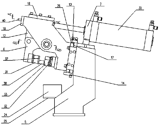
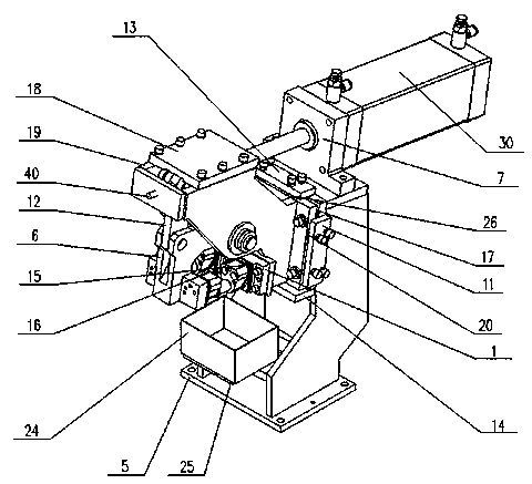
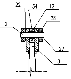
[0023] Such as Figure 1-Figure 4 As shown, a pneumatic punching device for a car body, the device includes a base 5, and one end of the upper part of the base 5 is provided with a bracket 7, and the bracket 7 is provided with a driving cylinder 30 that provides a power source for punching operation; A cylinder head 8 is provided, and the cylinder head 8 and the driving connecting plate 12 are hinged through the pin one 2, the driving connecting plate 12 and the turning arm 6 are hinged through the pin three 4, and the turning arm 6 and the base 19 are hinged through the pin two 3, That is, the driving cylinder 30, the driving connecting plate 12, and the overturning arm 6 form a four-bar linkage structure.

[0024] The cylinder head 8 is installed together with the dri...


PUM


Abstract

The invention relates to a pneumatic vehicle body punching device. A bracket is arranged at one end of the upper part of a base of the device; a driving cylinder is arranged on the bracket; a cylinder head of the driving cylinder is hinged to a driving connecting plate through a pin shaft 1; the driving connecting plate and a turnover arm are hinged through a pin shaft 3; and the turnover arm and a chassis are hinged through a pin shaft 2, that is, the driving cylinder, the driving connecting plate and the turnover arm form a four-connecting-rod structure. A three-way adjusting component formed by connecting a backup plate, a transverse adjusting mounting plate, a longitudinal adjusting mounting plate and an adjusting gasket is arranged on the other corresponding end of the upper part of the base; and the transverse adjusting mounting plate and the longitudinal adjusting mounting plate are fixedly connected with the chassis and the base through bolts. A punch arranged on the device is mounted on the turnover arm through a concave mold insert; a concave mold is mounted on the chassis through a concave mold insert; meanwhile, punching material collecting box mounting plates are arranged at the lower part of the base in parallel; and punching material collecting boxes are arranged on the punching material collecting box mounting plates. The device is simple in structure and convenient to operate, effectively realizes precise punching, saves energy, reduces noise, and is low in cost.

Description

technical field [0001] The invention relates to an automobile manufacturing equipment, in particular to an automobile body pneumatic punching device. Background technique [0002] At present, the competition in the automobile manufacturing industry is fierce. For example, there are many kinds of automobile stamping equipment, but the existing stamping equipment often has a complicated structure and poor application effect. The holes on the existing body stamping parts are usually punched out by the punch on the stamping die. When the model is updated, some installation holes need to be added. That is to say, the cost of directly adding the punch to the stamping die will be high, and the transformation is also difficult. Very large; for example, the common punching mechanism on body panels is an integrated gas-hydraulic punching device to meet the punching force of more than 1000kgf required for ordinary punching, and some are automatic laser cutting units. Institutions are ...

Claims


Application Information

Patent Timeline
Patent Type & Authority Applications(China)
IPC IPC(8): B21D28/26B21D43/20
CPCB21D28/26B21D43/20
Inventor 李昊武小明卢寿福岳怀宇董豪王大为赵锡茂
Owner 天津褔臻工业装备有限公司
Why Eureka
Try Eureka