Electronic control unit for motor vehicle braking systems

A technology of electronic control unit and hydraulic unit, which is applied in the direction of brakes, mechanical equipment, fluid pressure actuators, etc., to achieve the effects of favorable cooling, improved flexibility, and low manufacturing costs

Inactive Publication Date: 2007-01-17
CONTINENTAL TEVES AG & CO OHG
View PDF3 Cites 25 Cited by
  • Summary
  • Abstract
  • Description
  • Claims
  • Application Information

AI Technical Summary

Problems solved by technology

This construction also does not sufficiently meet the requirements placed on modern electrohydraulic control devices for motor vehicle braking systems

Method used


Image

  • Electronic control unit for motor vehicle braking systems
  • Electronic control unit for motor vehicle braking systems
  • Electronic control unit for motor vehicle braking systems

Examples


Embodiment Construction

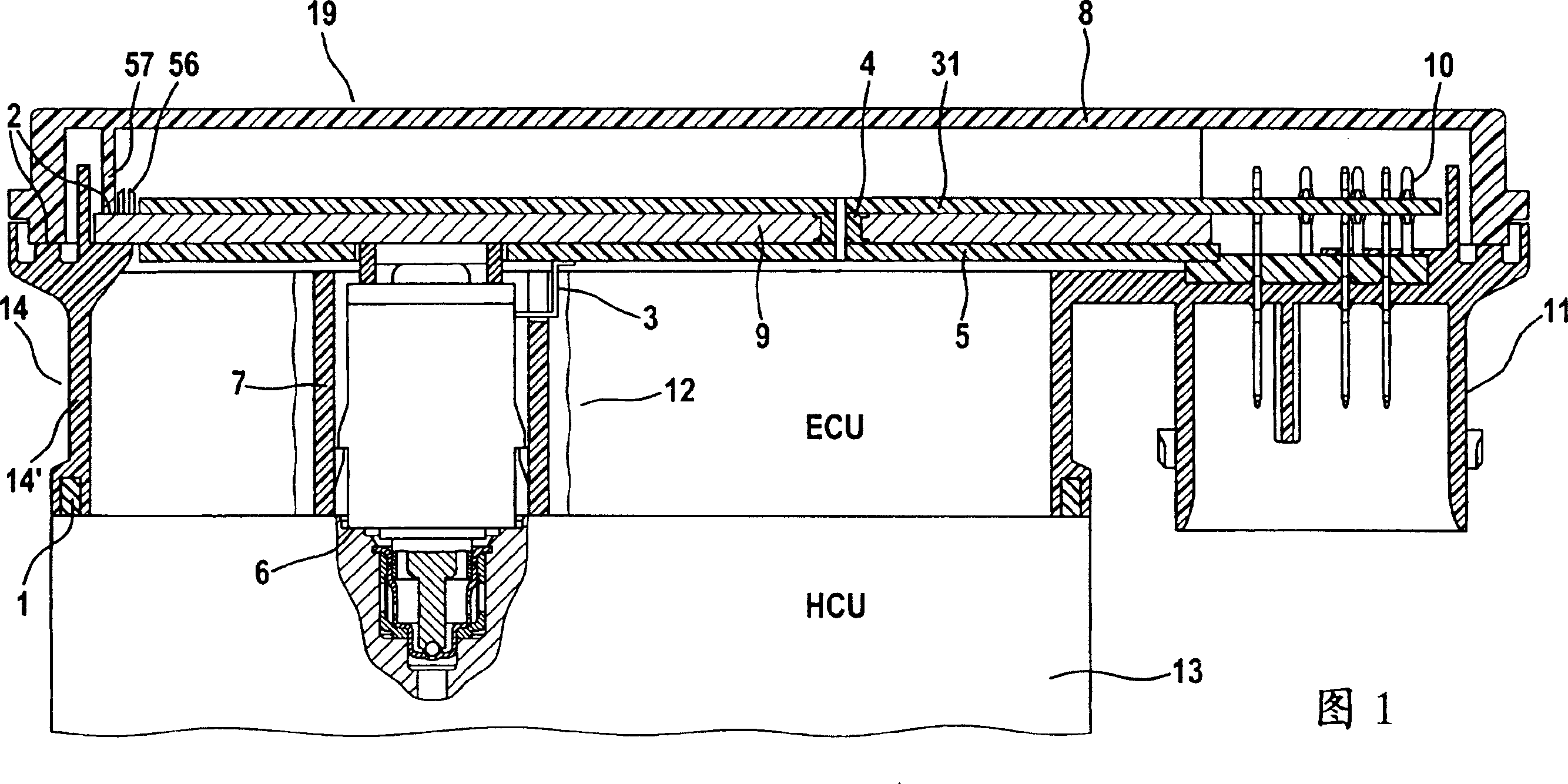
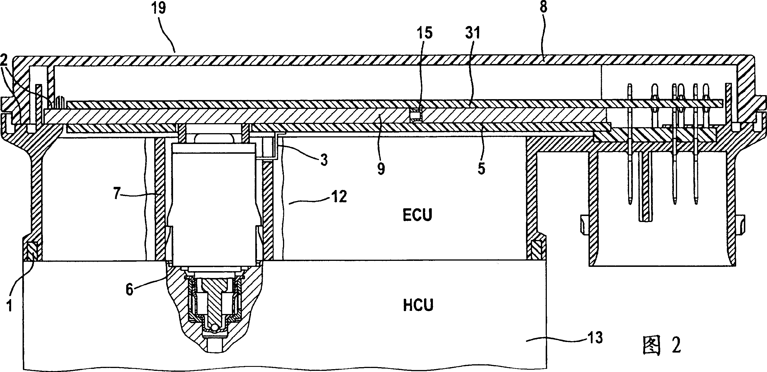
[0045]FIG. 1 shows the ECU 14 mounted on the HCU 13 . In the ECU, the assembly consisting of the printed circuit board 31 , the aluminum heat-conducting plate 9 and the further printed circuit board 3 is inserted into the controller housing 14 of the ECU. The housing 14 is sealed against the HCU in the region of the housing wall 14 ′ by means of the surrounding seal 1 . The sealing device 1 is preferably produced from a hose material and inserted into the housing groove. In the assembly consisting of the printed circuit boards 31 and 3 and the heat conducting plate 9, the cylindrical heat conducting body 4 (in this example only one heat conducting body is shown for simplicity) not only represents a heat conducting bridge, but also establishes the connection between the two printed circuit boards. Make electrical contact between the circuit boards 31 and 3. The heat conductor 4 is preferably made of the same material as the heat conductor plate 9 . This offers the advantage ...


PUM


Abstract

The invention relates to an electronic control unit (14), in particular in motor vehicle braking systems, which is connected to a hydraulic unit (13) by means of a magnetic connector. Said electronic control unit comprises: an area formed by the housing walls (14'), said area being used to receive several valve coils (12) which are arranged in said area, a housing cover (8, 35), at least one first circuit board (31, 5) which is used to receive electric and/or electronic components and an electric contact part and one first heat conducting plate (9, 32) which is used to guide heat away from the electronic components. The first heat conducting plate is connected in a flat manner to the first circuit board, and at least one heat connecting element (4, 15) which produces a thermal bridge between the first circuit board(s) and the first heat conducting plates, is provided. The invention also relates to a pump drive unit which co-operates with said control unit, whereby a motor base plate (22), for the electronic power components of the motor, is provided. The invention further relates to an electrohydraulic control device, wherein one or several elongate heat conducting elements (172) are arranged, said elements being in contact with the hydraulic block (13) and the cooling element (9) in order to form a thermal bridge. One longitudinal side of the heat conducting elements (172) is connected, in a positive or non-positive fit, to the hydraulic block or to the cooling element (9) and the opposite longitudinal sides thereof (1712) are arranged on the hydraulic block or the cooling element without the detachable non-positive fit connection.

Description

technical field [0001] The invention relates to an electronic control unit according to the preamble of claim 1 , a pump drive unit according to the preamble of claim 19 , a production method and a method according to the preamble of claims 24 and 25 electrohydraulic control device. Background technique [0002] EP 0 520 047 B1 (P 7129) discloses an ABS control device designed according to the principle of a so-called "magnetic plug" with a movable elastically held valve coil in the electronics housing . The electronic unit (ECU) with integrated printed circuit board and valve coils is connected with the valve block (HCU) including the valve housing of the brake assembly and other hydraulic components in a plug-in manner. The ECU also includes an integrated plug for connecting a connection cable, such as a wheel sensor cable. Control devices according to this principle have gained general acceptance in the automotive industry and are therefore widely used for various cont...

Claims


Application Information

Patent Timeline
Patent Type & Authority Applications(China)
IPC IPC(8): B60T8/36F15B13/00H05K7/20
Inventor W·克费尔M·尤尔根斯J·P·吉尔布R·魏里希M·菲林
Owner CONTINENTAL TEVES AG & CO OHG
Why Eureka
Try Eureka