Electrohydraulic pressure control device for automotive brake systems

A braking system and pressure control technology, applied in the direction of brakes, braking components, electrical components, etc., can solve the problems of making sufficient optimization for mass production

Inactive Publication Date: 2007-12-05
CONTINENTAL TEVES AG & CO OHG
View PDF2 Cites 19 Cited by
  • Summary
  • Abstract
  • Description
  • Claims
  • Application Information

AI Technical Summary

Problems solved by technology

This structure is currently not fully optimized for mass production due to the difficulty of producing most metal parts

Method used


Image

  • Electrohydraulic pressure control device for automotive brake systems
  • Electrohydraulic pressure control device for automotive brake systems
  • Electrohydraulic pressure control device for automotive brake systems

Examples


Embodiment Construction

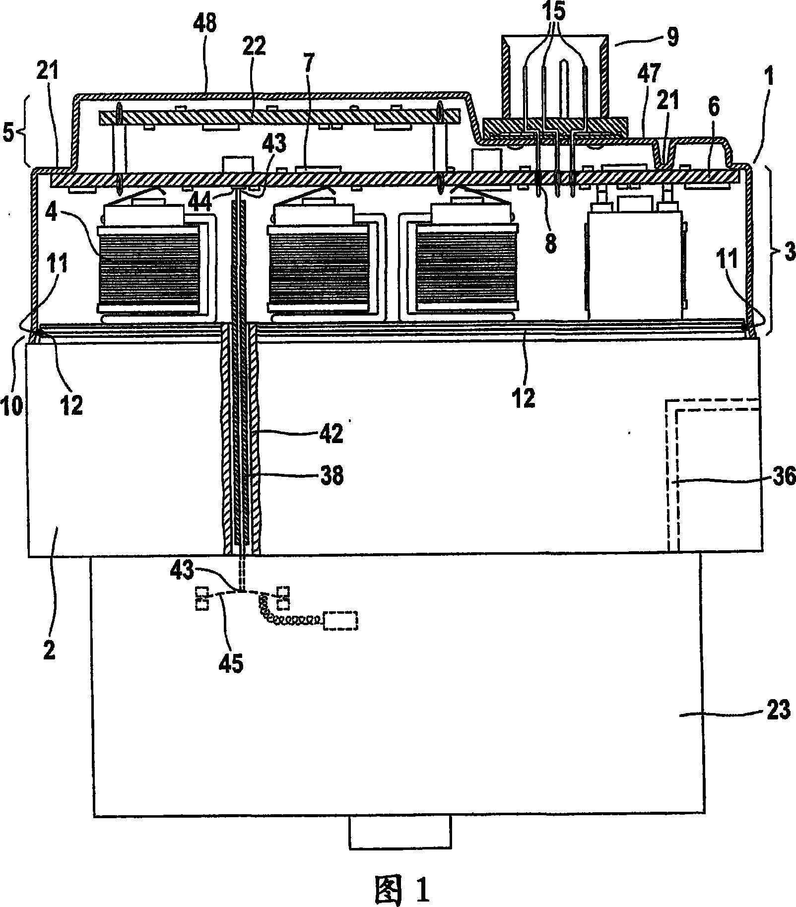
[0033] Figure 1 shows a combined ABS / ESP control. The controller 1 , the valve group 2 and the motor unit 23 represent a compact structural unit as installed in a motor vehicle for the control operation of the brakes generally. To this end, the valve block 2 is connected to a hydraulic line (not shown). The electronic control unit 7 on the printed circuit board 6 can engage the wire harness through the engaging plug 9 . Protrusions 21 on the cover push the printed circuit board 6 in the direction of the valve block 2 opposite the electrical contacts of the valve coil 4 .

[0034] The shape of the one-piece controller housing corresponds substantially to that of a thin-walled metal housing that is open at the bottom. Accordingly, the controller housing is composed of a housing volume area 3 and a housing cover area 5 .

[0035] The motor unit 23 is electrically connected through an insulated plastic adapter (motor plug) 38 with metal contained therein, which leads to the pum...


PUM


Abstract

The present invention relates to a electrohydraulic pressure control device for vehicle braking system. The device comprises a electron control unit (1) connecting with hydraulic pressure component (2). The control unit comprises a shell volume area (3) which can contain multiple valve loops (4), a shell cover area (5, 5') of the control unit shell, at least a first print circuit board (6) which is arranged with electric and / or electronic component as well as a electric coupling device (8) of conjugation plug, at least an adapter (38) of a motor unit which is used to joint hydraulic pressure unit, the adapter extends and passes through the hydraulic pressure component. The adapter comprises one or more electric pressure contact points (43) on one end or two, the electric pressure contact points push down on one or more interfaces (44, 45) through elastic force.

Description

technical field [0001] The invention relates to an electrohydraulic pressure control device for a motor vehicle braking system according to the preamble of claim 1 . Background technique [0002] EP 0520047 B1 (P 7129) discloses an ABS control device which is produced according to the so-called "electromagnetic plug" principle with a movable, elastically held valve coil in the electronics housing. An electronic control unit (ECU) with an integrated printed circuit board and valve coils can be plugged into a valve block (HCU) including valve housings and additional hydraulic components of the brake assembly. The ECU additionally includes integrated plugs that are often placed alongside for engaging connecting cables such as wheel speed sensor cables. Control devices according to this principle have found success in the automotive industry and are more widely used in various control tasks (such as ABS, ESP, etc.) of braking systems of motor vehicles. [0003] DE 10011807 A1 ...

Claims


Application Information

Patent Timeline
Patent Type & Authority Applications(China)
IPC IPC(8): B60T8/36B60T17/00H05K7/00
Inventor A・海泽W・埃勒尔
Owner CONTINENTAL TEVES AG & CO OHG
Why Eureka
Try Eureka