Key structure for large load motor iron core and rotating shaft transmitting torque, and installation method thereof

A technology for transmitting torque and large load, applied in the direction of magnetic circuit shape/style/structure, key connection, connecting member, etc., can solve the increase of equipment process requirements, the sliding of rotor core and shaft, and the inability of rotor punching and shaft to synchronize. Problems such as production, to achieve the effect of easy mass production and convenient assembly

Active Publication Date: 2008-10-29
上海电气集团上海电机厂有限公司
View PDF0 Cites 2 Cited by
  • Summary
  • Abstract
  • Description
  • Claims
  • Application Information

AI Technical Summary

Problems solved by technology

This method requires the outer diameter of the shaft to be matched with the inner diameter of the rotor punch, the rotor punch and the shaft cannot be produced synchronously, and the rotor core needs to be shrunk, which increases the requirements for the equipment process, and sometimes the rotor core and the shaft are in actual operation. shaft slipping

Method used


Image

  • Key structure for large load motor iron core and rotating shaft transmitting torque, and installation method thereof
  • Key structure for large load motor iron core and rotating shaft transmitting torque, and installation method thereof
  • Key structure for large load motor iron core and rotating shaft transmitting torque, and installation method thereof

Examples


Embodiment Construction

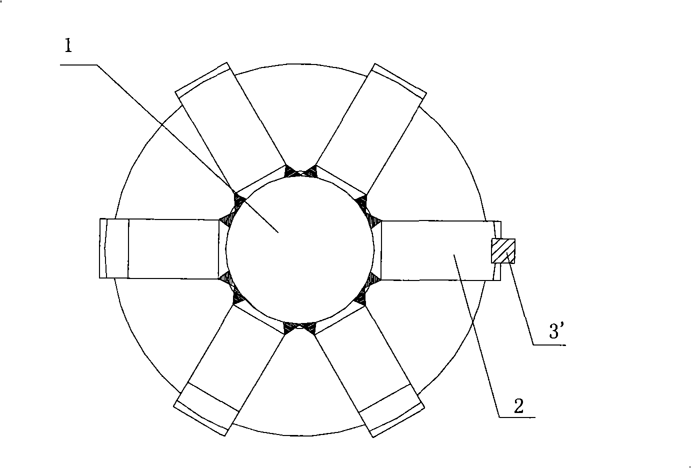
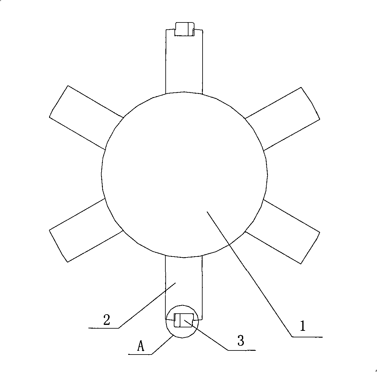
[0016] see figure 2 , a structure of a key for the torque transmission between the iron core of a large-load motor and the rotating shaft of the present invention, including at least one pair of key grooves (not shown in the figure) relative to 180° on the inner circle of the iron core, and evenly arranged on the outer peripheral surface of the motor rotating shaft 1. Several welding bars 2, key slots 20 corresponding to the key slots of the iron core provided on the outer circumference of the welding bars 2, and keys 3 embedded in the key slots of the two.

[0017] If the motor is single steering, a pair of key grooves 20 with a relative position of 180° are arranged on the outer circle of the welding rib 2 of the rotating shaft 1, and a pair of key grooves corresponding to the welding rib 2 are also arranged on the inner circle of the iron core. If the motor is required to have forward and reverse rotation, two pairs of key grooves 20 are arranged on the outer circle of the...


PUM


Abstract

The invention discloses a structure of a key of heavy-load motor iron core and rotating shaft transmission torque and an installation method thereof. The structure comprises an iron inner circle provided with at least a pair of key slots opposite to each other for 180 DEG; a plurality of welding webs uniformly distributed on the peripheral surface of a motor rotating shaft; key slots corresponding to the iron core key slots opened on outer rings of the welding webs and a key embedded in the key slots; wherein the key is composed of a pair of taper keys in parallel with the same structure; one lateral surface of each taper key is an inclined plane, and the other lateral surface of the taper key is step-shaped, namely, the middle lower part of the lateral surface is provided with a right angle shaped depression; the pair of key slots is matched with the opposite key slot walls of the iron core and the welding web through the step-shaped lateral surface, and the opposite inclined planes of the key slots are combined by the form of inclination complementation. The adoption of the structure of the key of heavy-load motor iron core and rotating shaft transmission torque of the invention can meet the mechanical strength of the motor when the overload is three times more than load; furthermore, the structure is convenient for assembly and easy for mass production.

Description

technical field [0001] The invention relates to a structure of a shaft key and an installation method of a key for torque transmission between an iron core and a rotating shaft, in particular to a structure and an installation method for a key for transferring torque between an iron core and a rotating shaft of a large-load motor. Background technique [0002] The key is mainly used to realize the circumferential fixation of the shaft and the parts on the shaft (such as gears and pulleys) to transmit torque; some can also realize the axial fixation of the parts on the shaft to transmit axial force; some can form a shaft Kinematic joints allow parts to slide on shafts. In the motor, the shaft is the motor shaft, and the part on the shaft is the armature core. In the metallurgical industry, the motor needs to drive loads such as the main rolling mill, coiler, punching and shearing machine, etc. These loads are mostly impact loads, and most of them are S9 working systems with ...

Claims


Application Information

Patent Timeline
Patent Type & Authority Applications(China)
IPC IPC(8): F16B3/00H02K1/22
Inventor 应伟航王斌
Owner 上海电气集团上海电机厂有限公司
Why Eureka
Try Eureka