Reversible, low cost, distributed optical fiber sensor with high spatial resolution

a distributed, optical fiber technology, applied in the field of spectroscopic based optical fiber sensors, can solve the problems of high detection cost, large number of optical fibers, and large number of optical fibers, and achieve the effects of improving optical fiber sensing systems, reducing complexity and manufacturing costs, and increasing the intensity of coupled light signals

Active Publication Date: 2009-01-06
EGALON CLAUDIO OLIVEIRA
View PDF37 Cites 25 Cited by
  • Summary
  • Abstract
  • Description
  • Claims
  • Application Information

AI Technical Summary

Benefits of technology

[0021]In accordance with the present invention a reversible, rugged, inexpensive, distributed optical fiber sensor with high spatial resolution is presented. The present invention can be used throughout the infrared, visible, and ultraviolet regions of the electromagnetic spectrum. The light source of the present invention provides an intense, and yet, cost effective means for probing the sensitive region of the fiber and produces a strong signal that can be easily detected.
[0025]In a preferred configuration, the probing light source is a UV LED, positioned adjacent to the optical fiber, and illuminating its sensitive region. The UV LED was chosen for several reasons. Primarily, the UV LED is an inexpensive and readily available source of excitation light, decreasing manufacturing expense. Secondly, recent LED technology has improved the intensity and decreased the size of the UV LED, allowing for a narrow, intense interrogating light beam. Additionally, the close proximity of the UV LED to the optical fiber allows for an increased intensity of the light signal, enabling the use of an inexpensive detector means, such as a silicon photo detector. Finally, the small LED size enables illumination of small regions of the cladding at multiple positions along the fiber length resulting in multiple independent sensing points with high spatial resolution. The technique also allows for the exact locating of the point of detection in a substance, showing a variation in the temperature and concentration of a chemical species along the length of the fiber.
[0026]An additional embodiment can include a reflector at the terminus of the optical fiber opposite of the detector means, increasing the light signal through redirecting backward propagating modes towards the detector means.
[0027]Yet another embodiment includes the use of a sensitive optical fiber with a tapered core, generally diverging towards the detector as the light signal propagates from the sensitive region of the optical fiber to the detector. This core configuration has the advantage of coupling more light into the fiber core than the other configurations increasing the signal of the device. With a tapered optical fiber, light rays that otherwise would radiate away from the fiber core are coupled as low loss bound modes and propagate for much longer lengths. This fiber can be manufactured using a drawing tower with a tapered glass preform. Alternatively, this fiber can also be manufactured manually by skilled in the shaping of glass.
[0028]In yet another embodiment, a plurality of light sources are positioned in a linear array along the length of the sensitive optical fiber, each light source consecutively, simultaneously, or independently emits a probing light transverse to the optical fiber core. The length of the array corresponds substantially to the length of the sensitive region of the optical fiber. This arrangement can be used to increase the overall light intensity of the coupled light signal.
[0033]The present invention is designed to substantially improve optical fiber sensing systems by, primarily, transversely positioning the light source, such as a UV LED or a white light LED, directly adjacent to the sensitive region of the sensitive optical fiber. This arrangement increases the intensity of the coupled light signal, decreases complexity and manufacturing costs, and, when using LEDs with small sizes, allows for the exact locating of the point of detection in a substance with a high spatial resolution.

Problems solved by technology

Each point along the fiber sensor requires a separate fiber optically communicating between the light source and the indicator, potentially creating a complex system of several of fibers.
The interaction between the evanescent tails of the excitation light with the sensitive cladding is very small requiring a high power source, an expensive detection scheme and / or a very long optical fiber.
Additionally, depending on the arrangement, the collinear alignment of the light source (such as a laser) with the axis of the optical fiber can be challenging, possibly requiring careful handling and calibration.
This arrangement requires an extremely long length of fiber in order to measure hundreds of species, increasing the overall size and complexity of the analyzing device.
Furthermore, the precision instruments can increase the overall cost of the instrument significantly.
The beam splitting technique make use of expensive high power lasers wherein the intensities decay as more beam splitters divert the excitation light to the sensitive coating.
A disadvantage is that the evanescent field of the excitation fiber is very weak delivering very little power to the sensing fiber.
Additionally, other methods of axial and transverse excitation are revealed; however, these methods were, on average, not cost effective.
Although it is acknowledged that these embodiments of '316 are operational, they are limited by complexity, manufacturing expense, and robustness of design.
This alternating removal of cladding increases the expense and complexity of mass production, limiting automation options in manufacture.
Additionally, other techniques utilized in industry require the use of expensive instrumentation such as an optical time domain reflectometer (OTDR).
Costing on the order of U.S. $20,000 or more, the OTDR adds considerable expense to any system that uses the axial excitation technique.
Also, the wavelengths availability of the OTDR systems are limited, restricting the choices of reagents that can be used with the sensor.
A further disadvantage of present systems is interference of the signal detected by the OTDR caused by inadvertent bends and physical irregularities in the waveguide material, varying the fiber's refractive index.
Furthermore, present techniques lack refinement of spatial resolution, on the order of approximately 10 cm.
However, past inventors failed to identify that side excitation, when properly done, can probe very small sections of a sensitive fiber leading to a sensor with a very high spatial resolution.
Previous endeavors also failed to provide a simpler excitation technique that leads to a low cost and rugged sensor.

Method used


Image

  • Reversible, low cost, distributed optical fiber sensor with high spatial resolution
  • Reversible, low cost, distributed optical fiber sensor with high spatial resolution
  • Reversible, low cost, distributed optical fiber sensor with high spatial resolution

Examples


Embodiment Construction

[0051]The following detailed description is of the best presently contemplated mode of carrying out the invention. This description is not to be taken in a limiting sense, but is made merely for the purpose of illustrating general principles of embodiments of the invention. The detailed description set forth below in connection with the appended drawings is intended as a description of presently-preferred embodiments of the invention and is not intended to represent the only forms in which the present invention may be constructed and / or utilized. The description sets forth the functions and the sequence of steps for constructing and operating the invention in connection with the illustrated embodiments. However, it is to be understood that the same or equivalent functions and sequences may be accomplished by different embodiments that are also intended to be encompassed within the spirit and scope of the invention.

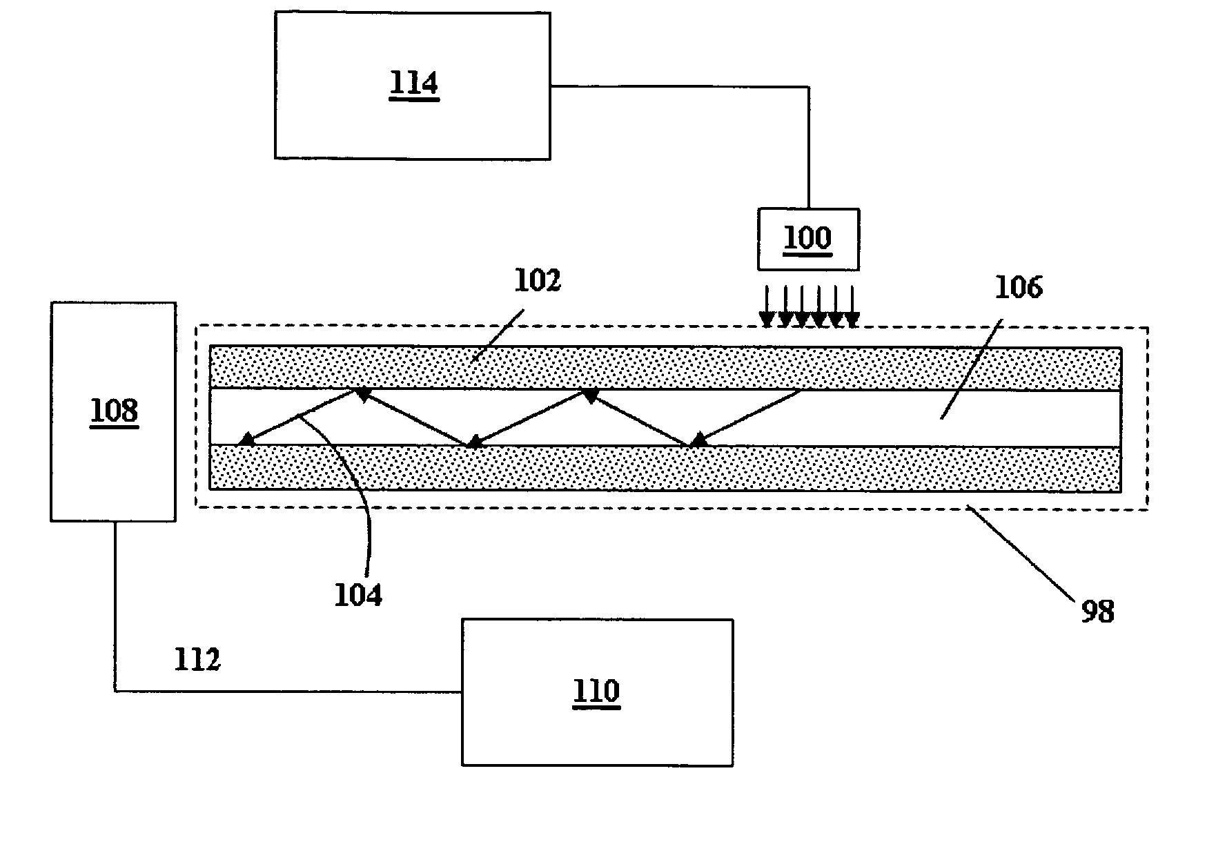
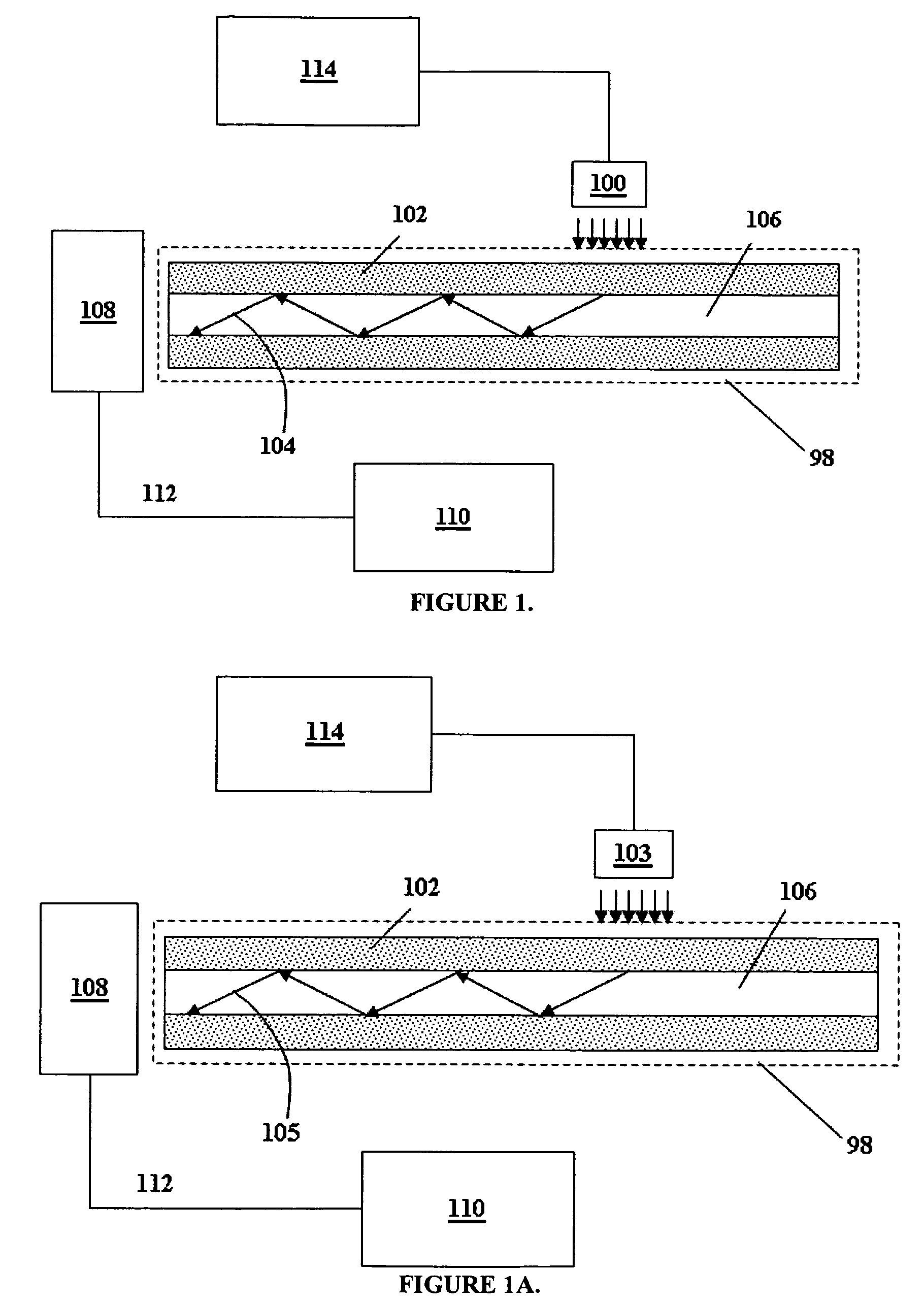
[0052]A block diagram of the sensor 98 is shown in FIG. 1. Accordingl...


PUM


Abstract

A spectroscopic based optical fiber sensor includes a sensitive optical fiber, a probing light source, a power supply, a detector means, a signal processing means, and a display means. The sensitive optical fiber is optically affected by the presence of at least one measurand. The probing light source, adjacent to the sensitive fiber, transversely illuminates the fiber from the outside. The probing light is modified by the sensitive fiber, coupled into the optical fiber core, either as bound modes or leaky modes, as a light signal and guided to a detector means located at the terminus of the optical fiber. The detector means correlates the intensity of the light signal with an electric signal and transmits the electric signal to the signal processing means, wherein the electric signal is correlated to the quantity being measured. The correlated quantity being transmitted and displayed on the display means.

Description

CROSS REFERENCE TO RELATED APPLICATIONS[0001]The present application claims priority from U.S. Provisional Application Ser. No. 60 / 676,121, filed Apr. 28, 2005.BACKGROUND[0002]1. Field of Invention[0003]This invention relates generally, to spectroscopic based optical fiber sensors. Particularly, this invention relates to absorption, fluorescent, phosphorescent and chemiluminescent based sensors.[0004]2. Description of Prior Art[0005]Spectroscopic based optical fiber sensors are used throughout numerous industries for the detection of temperature and various chemical species comprising a liquid or gas. These sensors have been developed using, primarily, two separate approaches: the optrode (or optode) and the distributed sensing approach.[0006]Optrodes are the simplest type of optical fiber sensors. Peterson et al, U.S. Pat. No. 4,200,110, discloses an indicator at the distal end of the fiber that is excited by a light source located in the proximal end. The excitation light travels ...

Claims


Application Information

Patent Timeline
Patent Type & Authority Patents(United States)
IPC IPC(8): G01J1/58
CPCG01N21/6428G01D5/35316G01N21/7703G01N21/648
Inventor EGALON, CLAUDIO OLIVEIRA
Owner EGALON CLAUDIO OLIVEIRA
Why Eureka
Try Eureka