Arrangement in region of mounting bracket in the front of motor vehicle

A technology for assembling brackets and motor vehicles, which is applied to vehicle components, transportation and packaging, and upper structure sub-assembly, etc., can solve problems such as damage to assembly brackets, and achieve simple cost, high rigidity and stability, and favorable manufacturing effects

Inactive Publication Date: 2016-04-20
VOLKSWAGEN AG
View PDF8 Cites 0 Cited by
  • Summary
  • Abstract
  • Description
  • Claims
  • Application Information

AI Technical Summary

Problems solved by technology

[0003] In practice, it has been found that in special, but rare driving si

Method used


Image

  • Arrangement in region of mounting bracket in the front of motor vehicle
  • Arrangement in region of mounting bracket in the front of motor vehicle
  • Arrangement in region of mounting bracket in the front of motor vehicle

Examples


Example Embodiment

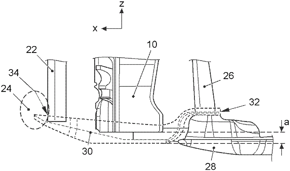
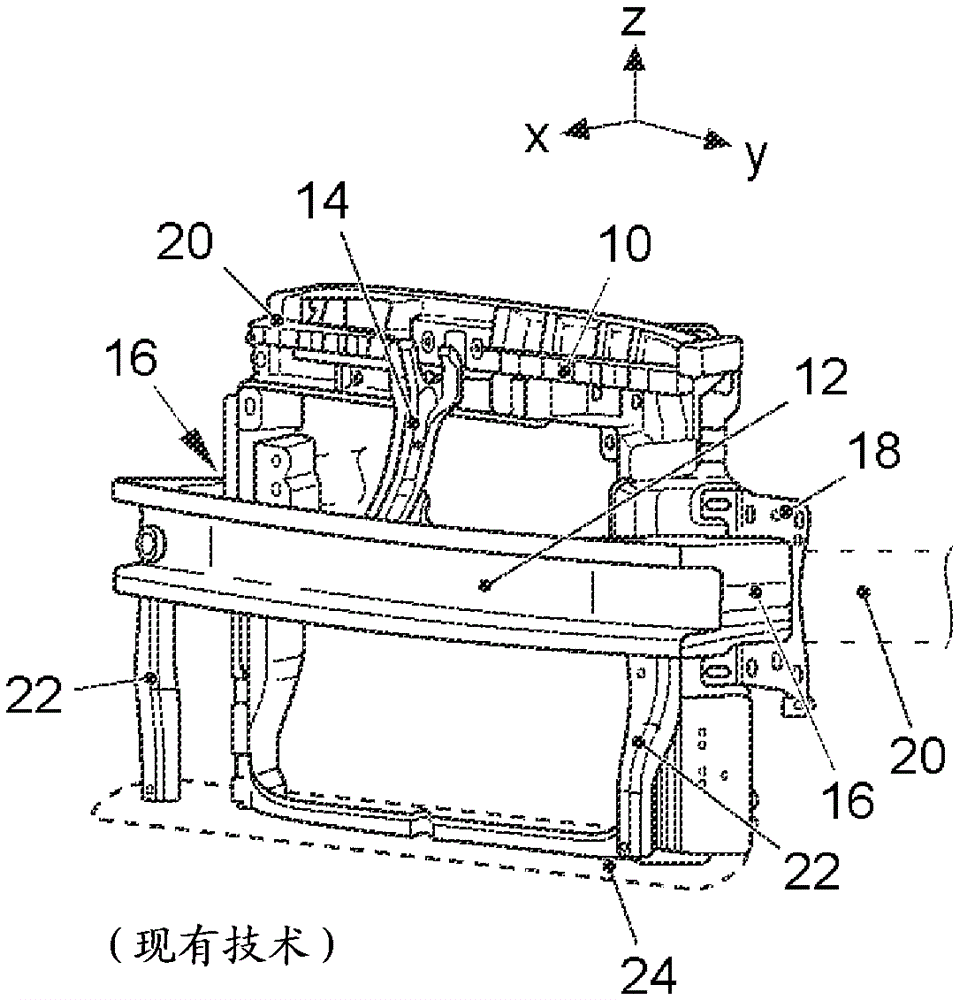
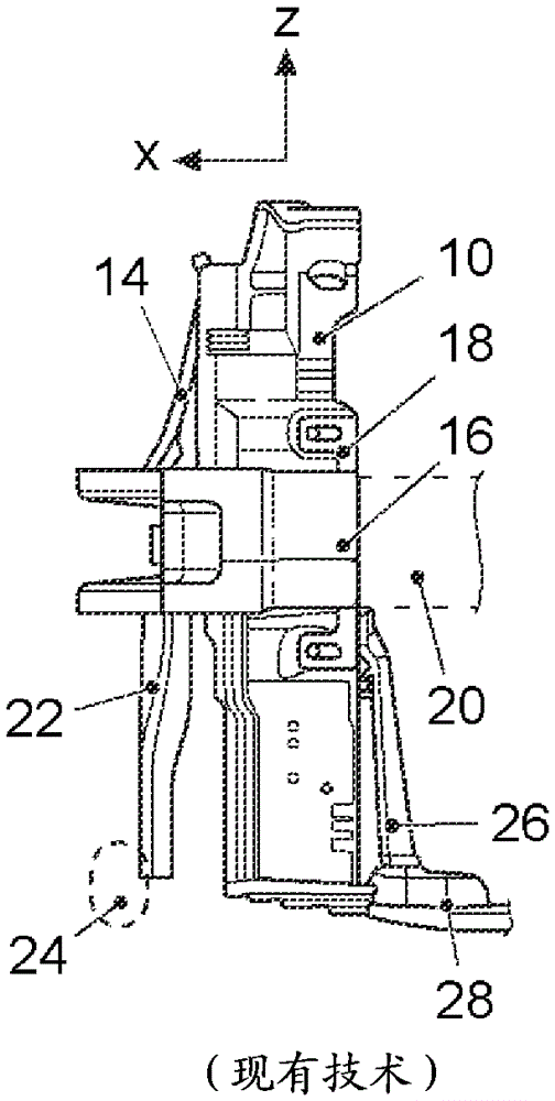
[0037] FIG. 1 shows the mounting bracket 10 together with other elements in the area of ​​the front compartment of a motor vehicle not shown. The mounting bracket 10 is configured as a closed frame and is used in particular to fasten a cooling unit arranged in a frame-shaped element, which is not shown in FIG. 1. When viewed in the longitudinal direction of the vehicle (x-direction), an upper cross member 12 is arranged before the mounting bracket 10. In particular, a cross member 12 extending in the vehicle transverse direction (y-direction) is connected to a tripod 14 extending upward from the cross member 12 in the vehicle vertical direction (z-direction). In addition, a deformation element 16 is arranged on the cross member 12, which is connected to the partition 18 on the back side. On the side of the partition 18 opposite the deformation element 16 of the cross beam 12, a longitudinal beam 20, which is indicated by a dashed line, is connected.

[0038] The cross beam 12 i...


PUM


Abstract

The invention relates to an arrangement in the region of a mounting bracket in the front of a motor vehicle. An object of the invention is to provide an arrangement in the region of a mounting bracket in the front of a motor vehicle, so that the mounting bracket is protected underneath from damage. The arrangement comprises a protective element (30), which is fixedly connected to elements, different from the mounting bracket (10), fixed on the vehicle body. The protective element (30) extends into a region directly adjacent to the mounting support (10) and below the mounting bracket (10) of the motor vehicle.

Description

technical field [0001] The invention relates to an assembly in the front compartment of a motor vehicle in the region of a mounting bracket. Background technique [0002] A front end structure for a commercial vehicle is known from DE 10 2012 019 933 A1. The vehicle front end structure includes an upper beam and a lower beam, and an upper longitudinal beam and a lower longitudinal beam connected with the upper beam and the lower beam. The upper and lower cross members are connected via two vertically extending support elements called struts. A cooler module is also shown in FIG. 1 . The cooler module is usually fastened to a mounting bracket, which surrounds the cooler module in a frame-like manner, but is not shown in DE 10 2012 019 933 A1. [0003] In practice, it has been found that in special, but rare driving situations, the mounting bracket is damaged by forces acting on it from below. Such forces arise in particular if the pavement moves the vehicle backwards and ...

Claims


Application Information

Patent Timeline
IPC IPC(8): B62D25/08
CPCB60R13/0861B62D25/085
Inventor M.伊波利蒂R.舒尔茨T.肖恩
Owner VOLKSWAGEN AG
Why Eureka
Try Eureka