
Pallet machine

A technology of pallet machine and pallet, which is applied in the direction of transportation and packaging, unstacking of objects, loading/unloading, etc., which can solve the problems of increasing the volume and cost of the whole machine, complicating the structure, and the self-heavyness of the pallet, etc., to achieve structural The effect of compactness, large load capacity and stable operation

Inactive Publication Date: 2016-04-20
GUANGDONG HANDSOME INTELLIGENT EQUIP CO LTD
View PDF8 Cites 6 Cited by
  • Summary
  • Abstract
  • Description
  • Claims
  • Application Information

AI Technical Summary

Problems solved by technology

[0002] Existing pallet machines generally output the pallets from bottom to top, which use chains and stepping motors for lifting control. When the pallets rise to the set position, the pallets are pushed out by the cylinder. The pallets of this structure When the pallet machine is stacking pallets, there is a gap between two adjacent pallets at equal distances. For large pallets, the above method is adopted. Due to the large weight of the pallets and the gap between the pallets and the pallet machine If the friction force between them is large, a driving motor and cylinder with large power are required, so the structure of the whole machine becomes complicated, and the volume and cost of the whole machine are increased.

Method used


Image

  • Pallet machine
  • Pallet machine
  • Pallet machine

Examples


Embodiment Construction

[0022] Embodiments of the present invention will be described in detail below in conjunction with the accompanying drawings.

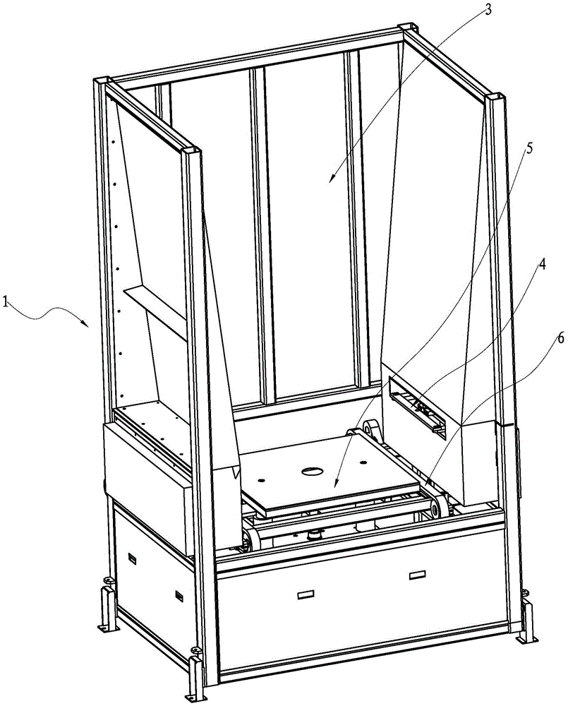
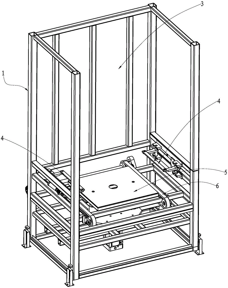
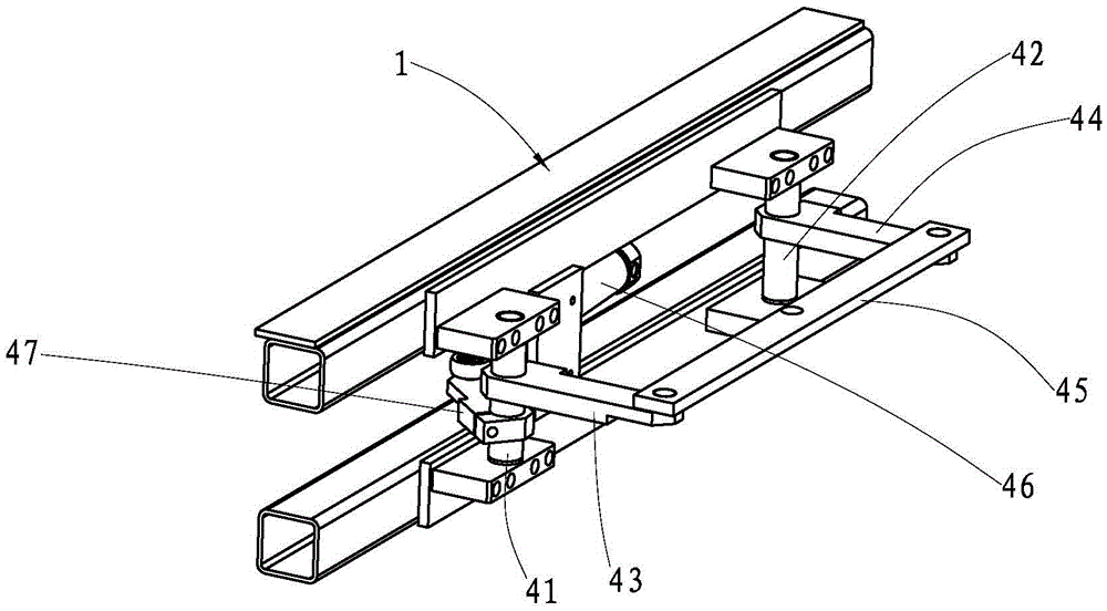
[0023] A pallet machine according to the present invention comprises a frame 1. A stacking space 3 for stacking pallets 2 is provided in the frame 1. The pallets 2 are directly stacked in the stacking space 3, and two adjacent pallets 2 are stacked up and down. There is no gap between them, therefore, more pallets 2 can be stacked, reducing refueling time and improving production efficiency. The two opposite sides of the lower part of the frame 1 are provided with a stacking space 3 that can be inserted into the stacking space 3 to block the pallets 2 and prevent the pallets 2. A locking mechanism 4 that slides down. The bottom of the frame 1 is provided with a support mechanism 5 that can be stretched up and down to support the pallet 2. The bottom of the frame 1 is also provided with a It is used to transport the supported pallet 2 out of the transmi...


PUM


Abstract

The invention discloses a pallet machine. Pallets are directly stacked inside a stack space and are not needed to be partitioned, clamping and blocking mechanisms are arranged at the two opposite sides of a frame, a parallel four-bar mechanism is adopted for each clamping and blocking mechanism, when the pallets are conveyed, the clamping and blocking mechanisms extend into the stack space for clamping the clamping grooves in the two opposite sides of the pallets, all the pallets in the stack space are clamped and positioned, and the pallet located at the lowermost position of the stack space is dropped to a transmission mechanism through a supporting mechanism and output from the bottom through the transmission mechanism. Therefore, the parallel four-bar mechanism is adopted for each clamping and blocking mechanism, so that the pallet machine has the advantages of being compact in structure, low in cost, stable in operation and large in bearing power.

Description

【Technical field】 [0001] The invention relates to pallet stacking equipment, in particular to a pallet machine. 【Background technique】 [0002] Existing pallet machines generally output the pallets from bottom to top, which use chains and stepping motors for lifting control. When the pallets rise to the set position, the pallets are pushed out by the cylinder. The pallets of this structure When the pallet machine is stacking pallets, there is a gap between two adjacent pallets at equal distances. For large pallets, the above method is adopted. Due to the large weight of the pallets and the gap between the pallets and the pallet machine If the frictional force between them is relatively large, a driving motor and a cylinder with relatively large power are required, which complicates the structure of the complete machine and increases the volume and cost of the complete machine. [0003] The present invention studies and proposes aiming at the deficiencies in the prior art. ...

Claims


Application Information

Patent Timeline
Patent Type & Authority Applications(China)
IPC IPC(8): B65G59/06
CPCB65G59/06B65G2814/0308
Inventor 罗躜黄安全陶国桢许庆培李有然
Owner GUANGDONG HANDSOME INTELLIGENT EQUIP CO LTD
Learn More