

Retractable charging device
A charging device, retractable technology, applied in the field of retractable charging devices, can solve the problems of charging wire winding, charging wire operation trouble, and safety hazards, etc., to achieve fast retractable, simple operation, and smooth retractable effects
- Summary
- Abstract
- Description
- Claims
- Application Information
AI Technical Summary
Problems solved by technology
Method used
Image

Examples
Embodiment 1
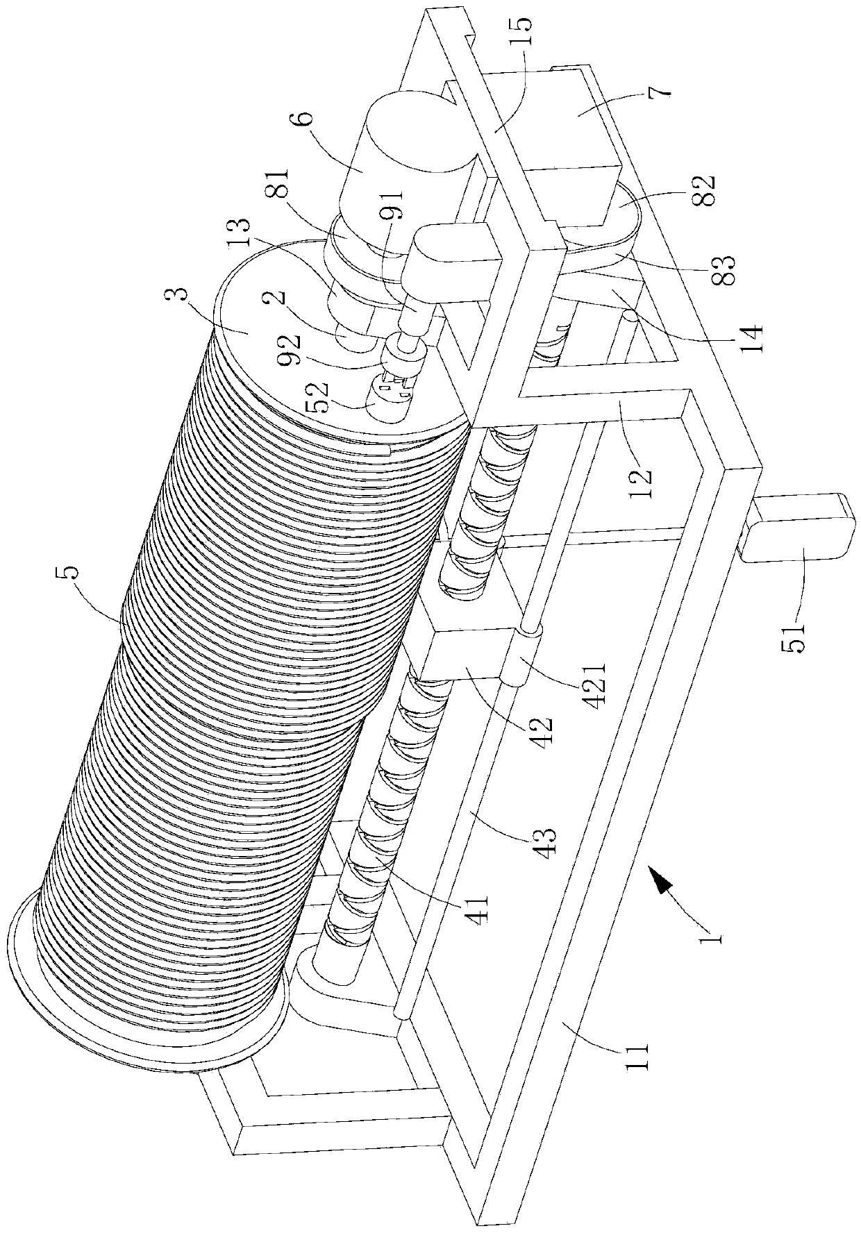
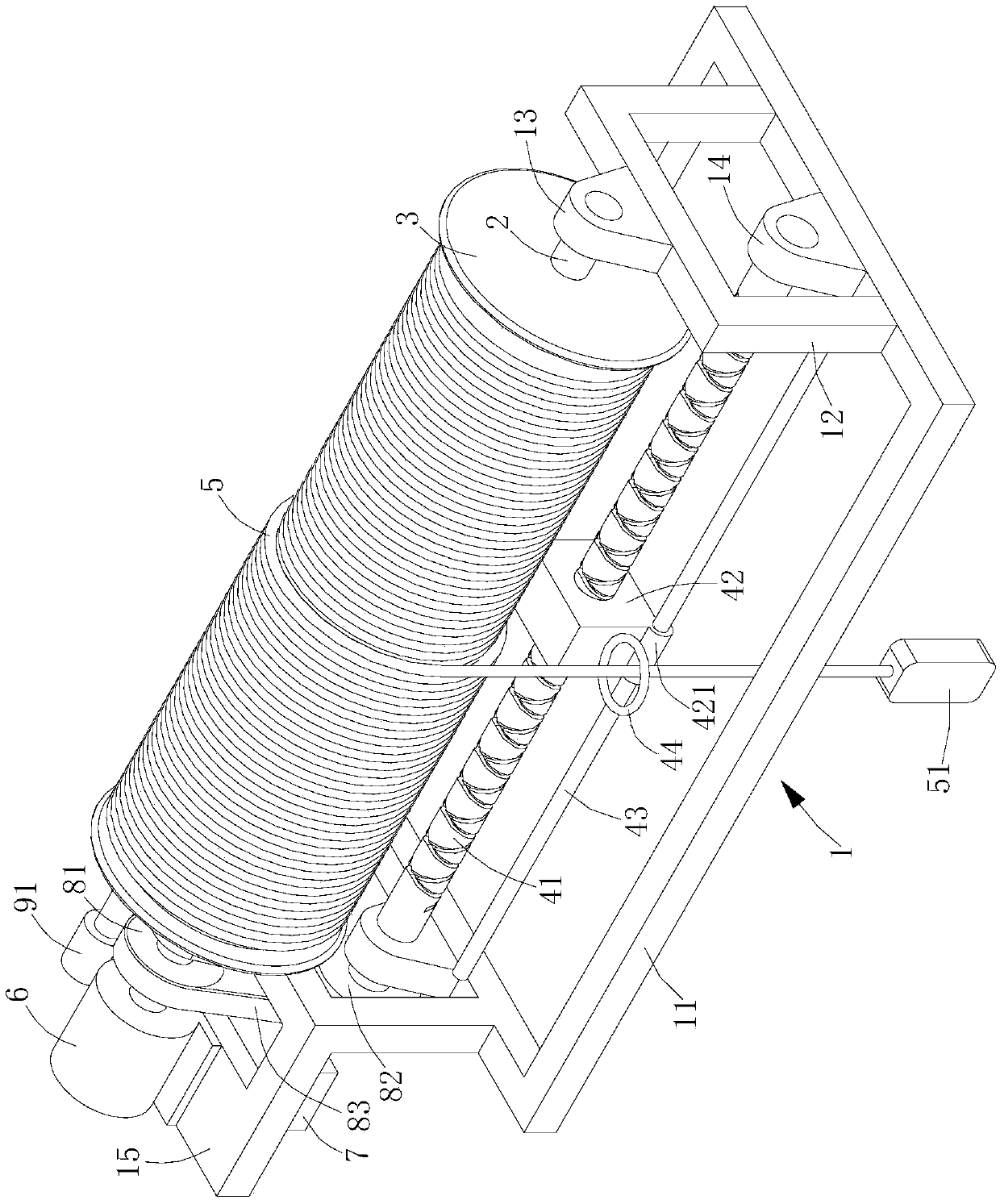
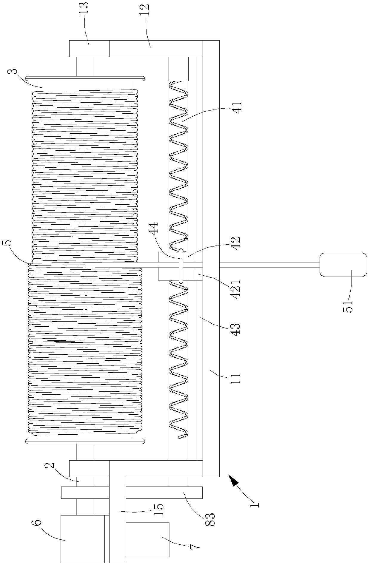
[0025] see figure 1 , figure 2 , image 3 and Figure 4 .
[0026] The retractable charging device of this embodiment includes a support frame 1, a rotating shaft 2, a bobbin 3, a lead screw 41, a lead screw nut 42, a lead screw guide rod 43 and a charging line 5, the rotating shaft 2 and the lead screw 41 They are all rotatably installed on the support frame 1, and the rotating shaft 2 and the lead screw 41 are parallel to each other. A power transmission mechanism is also provided between the rotating shaft 2 and the leading screw 41. The first pulley 81 and the second pulley 82 on the leading screw 41, and the drive belt 83 wound around the outside of the first pulley 81 and the second pulley 82, the bobbin 3 is fixed on the rotating shaft 2, so The lead screw guide rod 43 is fixed on the support frame 1 and is parallel to the lead screw 41, the lead screw nut 42 is screwed on the lead screw 41 and slides through the lead screw guide rod 43, and the lead screw nut 42 i...
Embodiment 2
[0036] see Figure 5 , Figure 6 and Figure 7 .
[0037] The structure of the retractable charging device of this embodiment is similar to that of Embodiment 1, the only difference is that this embodiment does not have an electric telescopic rod, a power plug and a power socket to turn on and off the power supply, but uses a side frame far away from the motor 6 12. A support block 16 is arranged on the top surface of the support block 16. Two conductive stators 101 arranged vertically at intervals are arranged on the top surface of the support block 16. The two conductive stators 101 are respectively connected to the positive and negative poles of the power supply. One end of the motor 6 protrudes from the first ear plate 13 and extends between the two conductive stators 101, and the opposite sides of one end of the rotating shaft 2 are covered with conductive plates 102 respectively. The positive and negative poles at the inner end are respectively connected to the two co...
PUM
 Abstract
Description
Claims
Application Information