A Flexible Lifting Positioning Clamping Device for a Wire Rope Drum

A positioning clamping and wire rope technology, which is applied in the direction of hoisting device, hoisting device, spring mechanism, etc., can solve the problems of the main shaft damage of the clamping mechanism, the damage of the clamping shaft wire rope disc, and complex structure, etc., and achieve the protection of the clamp. Tightening mechanism, improving clamping efficiency and accurate positioning

Inactive Publication Date: 2017-09-19
UNIV OF JINAN
View PDF10 Cites 0 Cited by
  • Summary
  • Abstract
  • Description
  • Claims
  • Application Information

AI Technical Summary

Problems solved by technology

[0002] At present, most of the wire rope take-up machines are ground-rail type wire rope take-up machines, while the ground-rail type wire rope take-up machines are mostly of gantry structure, and the lifting device of the wire rope reel mostly adopts a screw structure, which is complex and expensive
The positioning of the wire rope reel mainly depends on the outer circle of the wire rope reel, but the outer circle of the wire rope reel has been deformed during use, which makes the positioning of the wire rope reel inaccurate and causes serious damage to the main shaft of the clamping mechanism
[0003] When the clamping mechanism of the ground rail type wire rope take-up machine is working, it is often encountered that the force applied to the wire rope reel is too large, so that the clamping shaft in the clamping mechanism is firmly embedded in the wire rope reel, so that the clamping shaft should not leave the wire rope reel. , it often needs to be knocked down manually, which will cause great damage to the clamping shaft and the wire rope reel

Method used


Image

  • A Flexible Lifting Positioning Clamping Device for a Wire Rope Drum
  • A Flexible Lifting Positioning Clamping Device for a Wire Rope Drum

Examples


Embodiment Construction

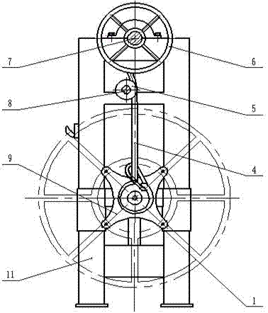
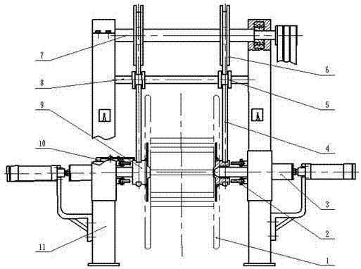
[0014] Such as figure 1 As shown, a wire rope reel flexible lifting positioning clamping device, the main structure includes an upper horizontal shaft 7, a lower horizontal shaft 8, a rope wheel 6, a lifting wire rope 4, a guide wheel 5, a fastening disc 9, a travel switch 10, and a column 11 , Clamping mechanism 3 and unloading mechanism 2. The sheave 6 is installed on the upper horizontal shaft 7, the lower horizontal shaft 8 is installed between the clamping mechanism 3 and the upper horizontal shaft 7, and the guide wheel 5 is installed on the On the lower horizontal axis 8 of the above, the fastening disc 9 is installed on the central position of the wire rope disc 1 . The clamping mechanism 3 is installed on the center of the upper longitudinal beam of the column 11, the travel switch 10 is installed on the top of the clamping mechanism 3, and the unloading mechanism 2 is installed on the clamping mechanism 3 inside. One end of the hoisting wire rope 4 is fixed on the...


PUM


Abstract

The invention provides a flexible lifting and positioning clamping device for steel wire rope spools. The device mainly structurally comprises an upper transverse shaft, a lower transverse shaft, a rope wheel, a lifting steel wire rope, a guide wheel, a fastening disc, a travel switch, a clamping mechanism and an unloading mechanism, wherein the rope wheel is installed on the upper transverse shaft, the guide wheel is installed on the lower transverse shaft, the travel switch is arranged at the top of the clamping mechanism, the unloading mechanism is arranged at the inner side of the clamping mechanism, one end of the lifting steel wire rope is fixed onto the rope wheel and coils partially, the other end of the lifting steel wire rope winds the fastening disc, and a hook hooks the lifting steel wire rope. Compared with a lifting device on an existing ground rail type steel wire rope coiler, the device has the characteristics that with the lifting steel wire rope, the up-down flexible positioning of a steel wire rope spool can be realized by virtue of elasticity of the lifting steel wire rope, and as the lifted steel wire rope spool can swing front and back as well as left and right, the flexible positioning all around is further realized, so that the clamping efficiency of the steel wire rope spools is enhanced greatly, and the clamping mechanism can protect a take-up and pay-off device effectively.

Description

technical field [0001] The invention relates to the field of mechanical devices, in particular to a flexible lifting positioning and clamping device for a wire rope reel. Background technique [0002] At present, most of the wire rope take-up machines are ground-rail type wire rope take-up machines, and most of the ground-rail type wire rope take-up machines are of gantry structure, and the hoisting device of the wire rope reel mostly adopts a screw structure, which is complicated and expensive. The positioning of the wire rope reel mainly depends on the outer circle of the wire rope reel, but the outer circle of the wire rope reel has been deformed during use, which makes the positioning of the wire rope reel inaccurate and causes serious damage to the main shaft of the clamping mechanism. [0003] When the clamping mechanism of the ground rail type wire rope take-up machine is working, it is often encountered that the force applied to the wire rope reel is too large, so th...

Claims


Application Information

Patent Timeline
Patent Type & Authority Patents(China)
IPC IPC(8): B66F11/00B66D1/56B65H75/22
CPCB65H75/22B66D1/56B66F11/00
Inventor 田相省王慧赵萍客圣俊孙令东
Owner UNIV OF JINAN
Why Eureka
Try Eureka