
Dynamic pressure lubricating method and structure

A lubricating structure and lubricant technology, applied in the direction of gear lubrication/cooling, transmission parts, belts/chains/gears, etc., can solve the problem of affecting the transmission accuracy and transmission efficiency of the push rod mechanism, cannot produce convergent fluid wedges, and cannot form Wedge-shaped lubricating film and other problems, to achieve the effect of improving transmission accuracy and transmission efficiency, stable position, and increased working life

Inactive Publication Date: 2016-04-20
BEIJING UNION UNIVERSITY
View PDF7 Cites 1 Cited by
  • Summary
  • Abstract
  • Description
  • Claims
  • Application Information

AI Technical Summary

Problems solved by technology

However, since the sliding shoe in this invention always maintains surface contact with the disk, its dynamic pressure lubrication effect is very limited. During the relative motion between the shoe and the disc, a convergent fluid wedge cannot be generated, and thus a wedge-shaped lubricating film cannot be formed. Therefore, the dynamic pressure lubrication structure and method also have technical defects such as large frictional resistance and easy to cause wear of the friction pair. Obviously, this Will directly affect the transmission accuracy and transmission efficiency of the push rod mechanism

Method used


Image

  • Dynamic pressure lubricating method and structure
  • Dynamic pressure lubricating method and structure
  • Dynamic pressure lubricating method and structure

Examples


Embodiment 1

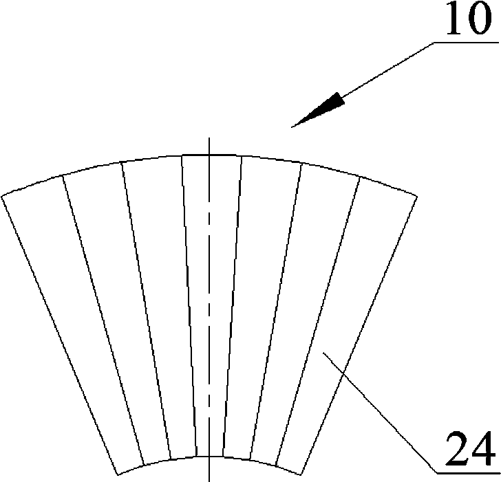
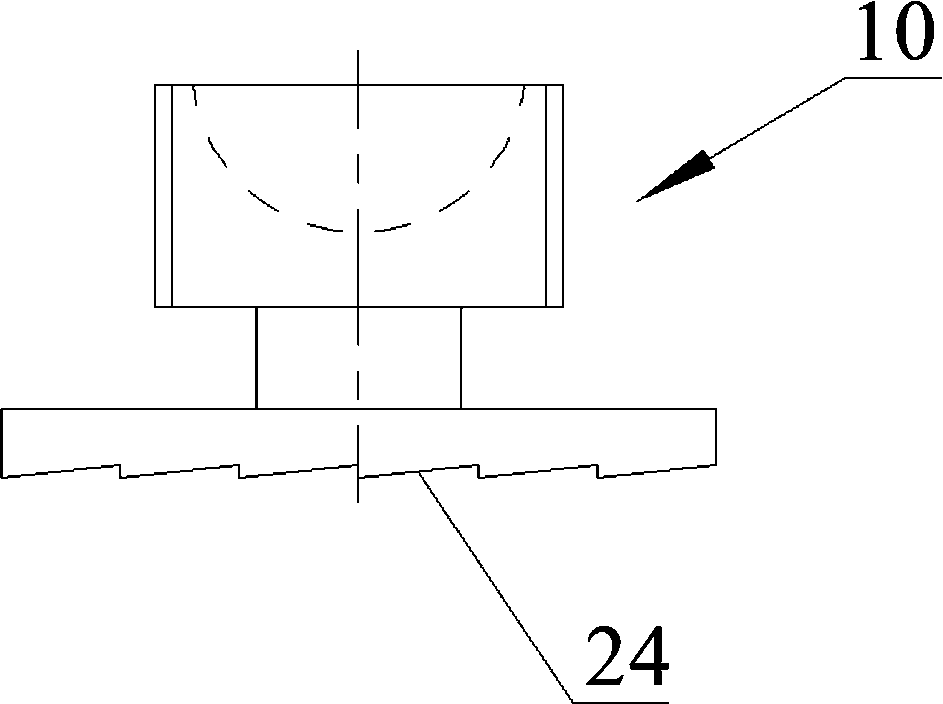
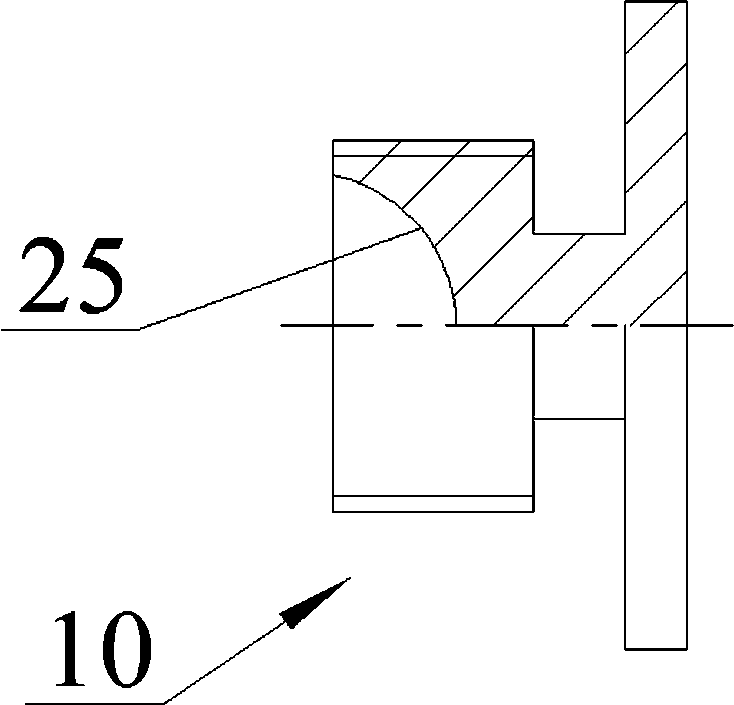
[0066] One aspect of the present invention provides a method of dynamic pressure lubrication. The structure for implementing the method includes a dynamic pressure lubrication shoe 10 and a relative movement plane. A plurality of slopes 24 are radially provided on the bottom surface of the bottom surface, and a convergent fluid wedge is formed between the plurality of slopes 24 and the relative motion plane, and a lubricant is provided in the convergent fluid wedge, including the following steps:

[0067] Step a. On the premise that the lubricant has sufficient viscosity, a wedge-shaped lubricating film can be generated between the several inclined surfaces 24 and the relative motion plane, so as to form sufficient bearing pressure to bear the external load;

[0068] Step b. When the speed of the relative movement between the several inclined surfaces 24 and the relative motion plane reaches a certain size, the lubricant between the two relatively moving friction surfaces will ...

Embodiment 2

[0072] A method and structure of dynamic pressure lubrication, which is similar to Embodiment 1, except that: the liquid lubricant uses synthetic lubricating oil.

Embodiment 3

[0074] A dynamic pressure lubrication method and structure, which are similar to Embodiment 1, except that: the fluid lubricant is a gas lubricant, and the gas lubricant is air.


PUM


Abstract

The invention relates to a dynamic pressure lubricating method. A structure for implementing the method comprises a dynamic pressure lubricating piston shoe (10) and a relative motion plane; the appearance of one end of the dynamic pressure lubricating piston shoe (10) is in an annular sector shape, a plurality of slopes (24) are arranged on the bottom face of the annular sector shape in the radial direction, a convergence type fluid wedge is formed between the multiple slopes (24) and the relative motion plane, and a lubricating agent is arranged in the convergence type fluid wedge. The dynamic pressure lubricating method includes the following steps: (a) a friction pair can generate a wedge-shaped lubricating film on the premise that the lubricating agent has sufficient viscosity; (b) the lubricating agent supports structures of multiple slopes (24); and (c) the multiple slopes (24) are separated from the relative motion plane, and the dynamic pressure lubricating state is formed. Compared with the prior art, the dynamic pressure lubricating method has the beneficial effects that the frictional resistance of the friction pair can be substantially reduced, abrasion of the friction pair can be greatly reduced, the transmission accuracy and the transmission efficiency of the dynamic pressure friction pair can be substantially increased, and the working service life can be substantially prolonged.

Description

technical field [0001] The invention relates to a lubrication method and structure of a friction pair, in particular to a dynamic pressure lubrication method and structure. Background technique [0002] Chinese invention patent ZL200910210481.8 discloses a swash plate guide rod type continuously variable transmission, which belongs to the technical field of mechanical transmissions. According to this invention, the swash plate guide rod type continuously variable transmission is composed of an active mechanism, an output mechanism, and a box (15), and the active mechanism is composed of a swash plate (12) with adjustable inclination and more than three guide rods arranged at equal angles. , one end of the three guide rods has a helical gear that can rotate in one direction, and the other end is abutted on the swash plate surface, and can perform circular sliding on the swash plate surface. The output mechanism is composed of a unidirectionally rotating output shaft (2) and ...

Claims


Application Information

Patent Timeline
IPC IPC(8): F16H57/04
CPCF16H57/0473F16H57/0487
Inventor 雷红李立新孙建东
Owner BEIJING UNION UNIVERSITY
Learn More