
An air-conditioning indoor unit air inlet and outlet structure

An air-conditioning indoor unit and air outlet technology, which is applied in air-conditioning systems, space heating and ventilation, space heating and ventilation details, etc., can solve problems such as the effect of shutter closure, influence on meshing, and hidden dangers of spring durability.

Active Publication Date: 2019-08-09
GUANGDONG CHIGO AIR CONDITIONING
View PDF9 Cites 0 Cited by
  • Summary
  • Abstract
  • Description
  • Claims
  • Application Information

AI Technical Summary

Problems solved by technology

[0004] These two existing technologies mainly have the following problems: (1) The rack-and-pinion mechanism requires high manufacturing and installation accuracy. If the rack-and-pinion mechanism is installed on the housing for meshing, the meshing parts are prone to offset, and at the same time, the meshing The influence of the backlash in the position causes the opening angle of the shutter to be inconsistent; (2) foreign matter is easy to enter the meshing part, which affects the stable meshing; (3) the wear of the rack and pinion has an impact on the closing of the blind; (4) the rack and pinion mechanism needs more Large tooth feed can complete the opening and closing of the blinds, which not only increases the rotation of the motor, but also requires high-precision rotation control, and at the same time affects the appearance ratio and structural design of the whole machine, which have become extra for the designer. burden; (5) There are hidden dangers in the durability of the spring, and the blinds may not close tightly after long-term use; (6) The tension of the spring and the torque of the stepping motor need to be determined according to the weight of the blinds, etc.

Method used


Image

  • An air-conditioning indoor unit air inlet and outlet structure
  • An air-conditioning indoor unit air inlet and outlet structure
  • An air-conditioning indoor unit air inlet and outlet structure

Examples


Embodiment Construction

[0018] First, the technical solution claimed by the present invention will be further described in detail with reference to the drawings and specific embodiments.

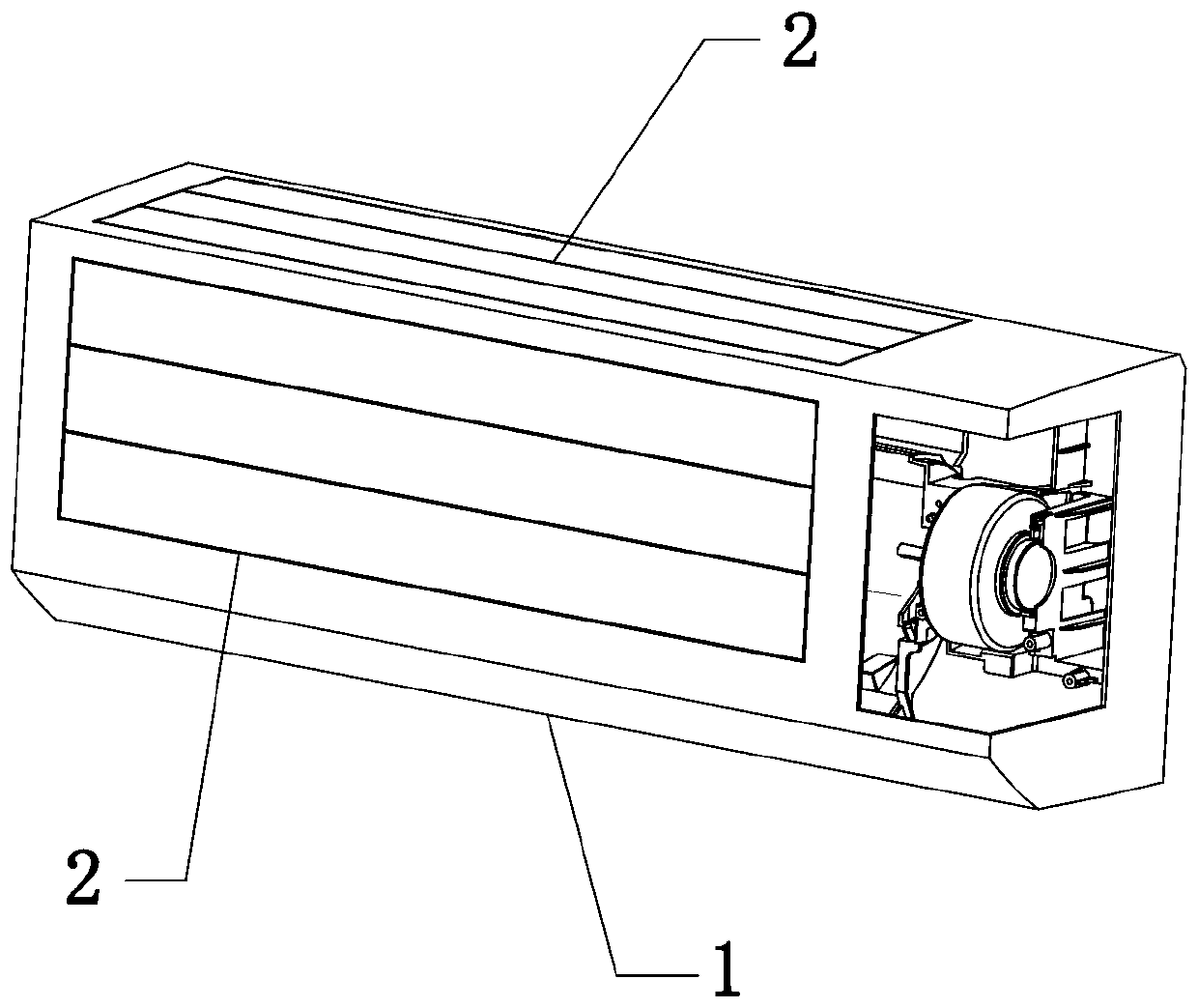
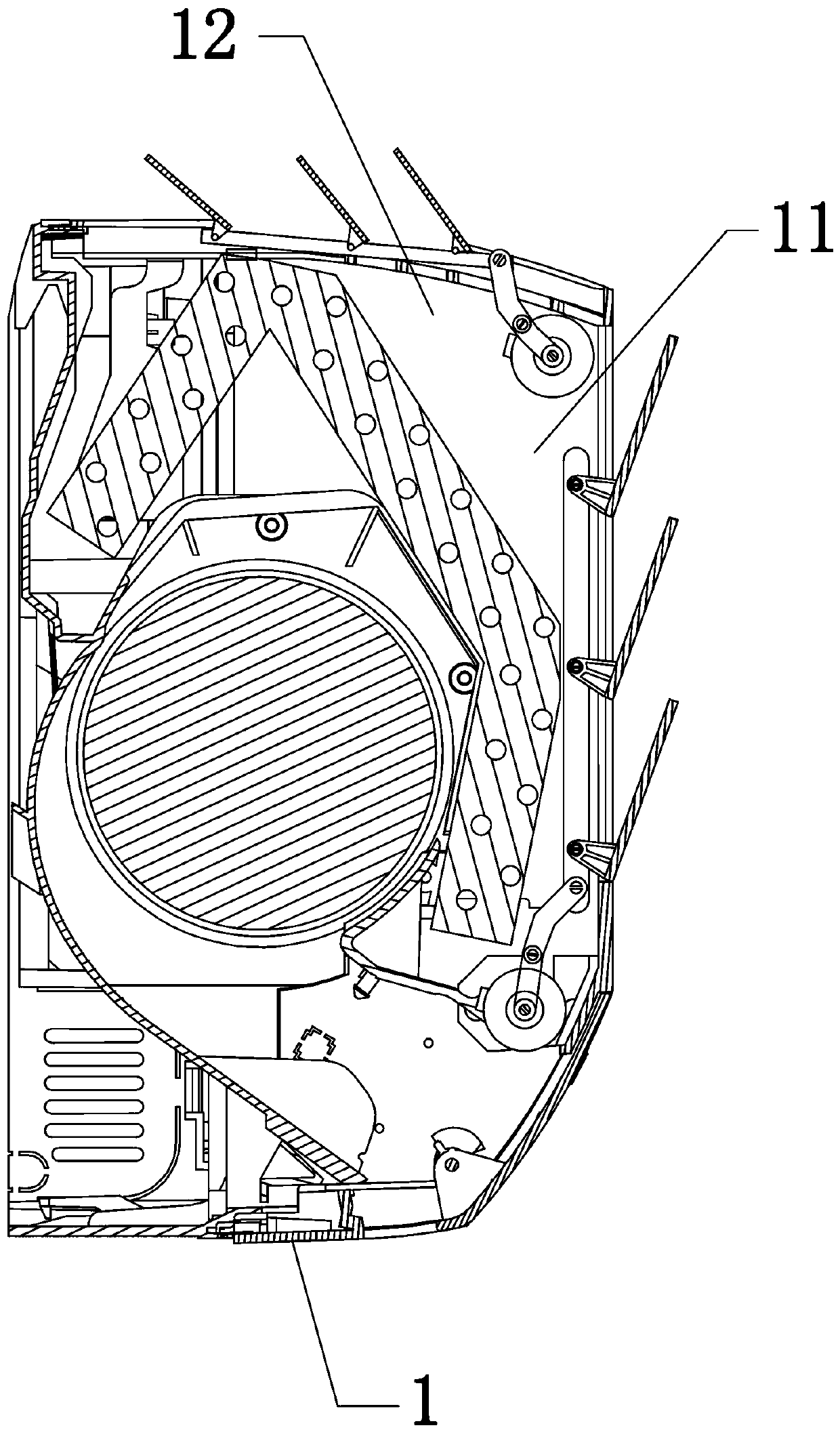
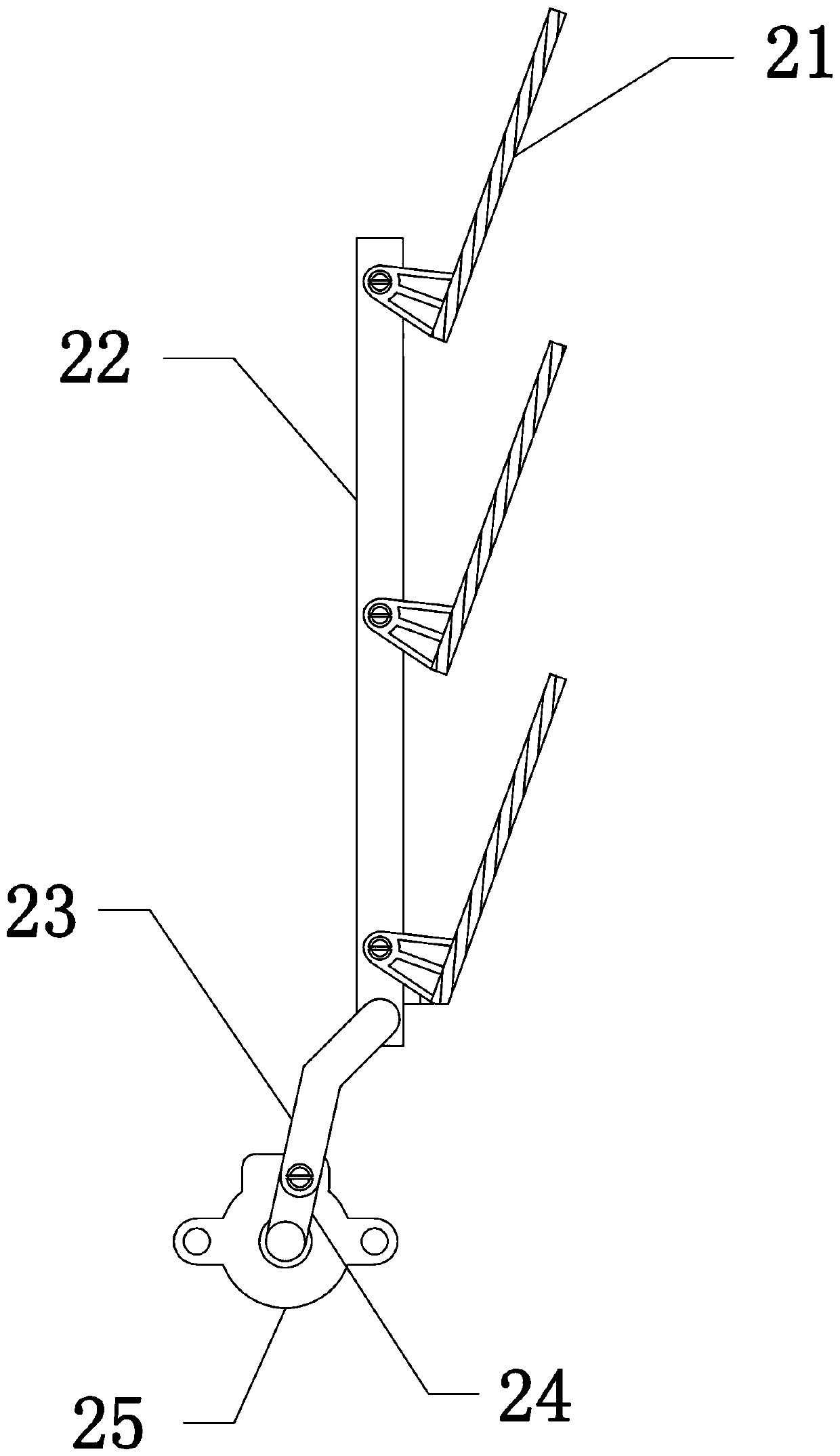
[0019] See Figure 1 to Figure 5 As shown, the air inlet and outlet 11 structure of the indoor unit of the air conditioner in this embodiment includes an air outlet 11 opened on the front of the body 1 and an air inlet 12 on the upper side. The air inlet 12 and the air outlet 11 are provided with shutters 2, and the shutters 2 include There are multiple blades 21, a sliding rod 22 that is simultaneously hinged with multiple blades 21, a connecting rod 23 hinged to the sliding rod 22, a crank 24 hinged to the other end of the connecting rod 23, and a drive for driving the crank 24 to rotate in parallel. For the motor 25, in this embodiment, the material of the blade 21, the sliding rod 22, the connecting rod 23 and the crank 24 is engineering plastic, which has good mechanical properties and processing characteristics,...


PUM


Abstract

The invention discloses an air inlet and outlet structure of an indoor air conditioner. The air inlet and outlet structure comprises an air outlet formed in the front of the indoor air conditioner, an air inlet formed in the upper side surface of the indoor air conditioner and blind windows arranged at the air inlet and the air outlet, wherein each blind window comprises a plurality of vanes, a sliding bar simultaneously connected to the plurality of vanes, a connecting rod articulated with the sliding bar, a crank articulated with the other end of the connecting rod and a driving motor for driving the crank to rotate around a parallel; the sliding bar, the connecting rod, and an articulated shaft and a rotating shaft of the crank are perpendicular to the same plane to form a crank sliding block mechanism; the two sides of each vane are in pivoted connection with the air inlet / the air outlet; and the crank sliding block mechanism formed by the sliding bar, the connecting rod and the crank drive the vanes to open and close.

Description

Technical field [0001] The invention relates to the technical field of air conditioners, in particular to an air inlet and outlet structure of an indoor unit of an air conditioner. Background technique [0002] In the field of air-conditioning indoor units, the upper side has an air suction port, and the lower side has an air discharge port for blowing out heat-exchanged air. On the side of the air suction port, there are blinds, which are opened when the air conditioner is running, and closed when the air conditioner stops running. In this way, it not only achieves the effect of increasing the air volume during operation to improve the ability, and blocking pollutants from entering the air conditioner when it is stopped, while improving the appearance quality. [0003] In the prior art, the shutters are opened and closed through a rack and pinion mechanism, and the device is disclosed in JP 9-210401. The main principle is: each shutter is installed and connected to a linkage pla...

Claims


Application Information

Patent Timeline
Patent Type & Authority Patents(China)
IPC IPC(8): F24F1/0011F24F13/15
CPCF24F1/0007F24F1/0011F24F13/1426F24F13/15F24F2013/1433
Inventor 潘国清胡根邓安哲
Owner GUANGDONG CHIGO AIR CONDITIONING
Learn More