Interlocking binding machine drilling device and binding machine

A drilling device and binding machine technology, applied in binding, metal processing, etc., can solve problems such as poor rotation stability, increased external dimensions, and increased costs

Active Publication Date: 2016-03-30
DELI GROUP CO LTD
View PDF10 Cites 0 Cited by
  • Summary
  • Abstract
  • Description
  • Claims
  • Application Information

AI Technical Summary

Problems solved by technology

The drilling structure and hot riveting mechanism that work independently are also present. There are fully automatic drilling and hot riveting structures. On the basis of the above structure, the lifting motor and the related linkage structure are added to drive the motor base for automatic lifting movement. The unique lifting motor and its interlocking structure make the overall structure of the binding machine more complex and increase the overall size, and bring about an increase in cost
The above-mentioned interlocking structure has the disadvantages of relatively complex structure and poor rotational stability.
At the same time, due to the need for manual operation, the quality of hot riveting is limited by the degree of human compaction, which cannot meet the direction of automation development.

Method used


Image

  • Interlocking binding machine drilling device and binding machine
  • Interlocking binding machine drilling device and binding machine
  • Interlocking binding machine drilling device and binding machine

Examples


Embodiment Construction

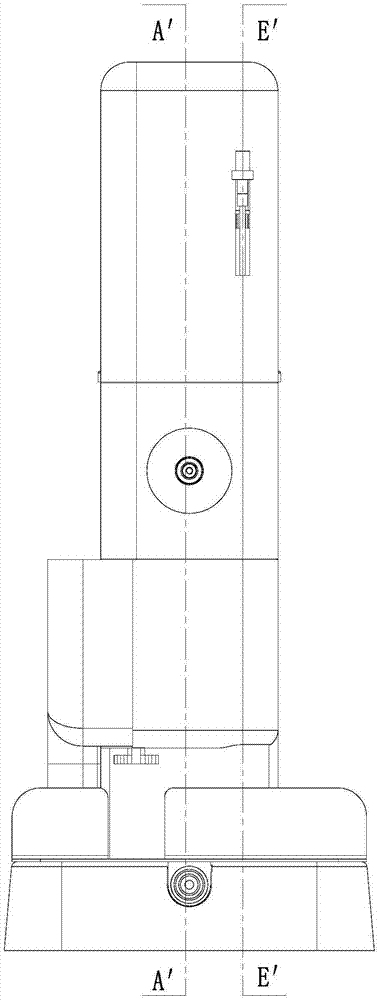
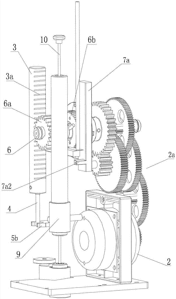
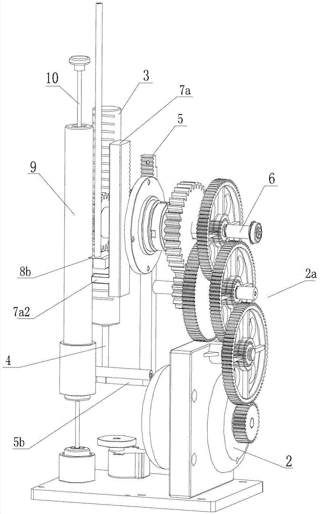
[0059] Such as Figure 1 to Figure 37 As shown, a drilling device for an interlocking binding machine includes a first motor 2 on a fixed machine base 1, a horizontal rotating shaft 6, a drilling guide post 3, a paper pressing guide post 5, and a drill is arranged at the lower end of the drilling guide post 3. Knife 4, platen platen 5b is set at the lower end of platen guide post 5, first motor 2 is provided with reduction gear set and is connected with horizontally arranged horizontal rotating shaft 6, and horizontal rotating shaft 6 is provided with first driving gear 6a and second driving gear 6b, horizontal The rotating shaft 6 is fixedly connected with the first driving gear 6a, and a torsion spring 7 is arranged between the horizontal rotating shaft 6 and the second driving gear 6b ​​to be rotatably connected. The side and the side wall are provided with guide teeth 3a, 5a respectively engaged with the first driving gear 6a and the second driving gear 6b.

[0060] Such ...


PUM


Abstract

The invention relates to a linked bookbinding machine drilling device which comprises a motor arranged on a fixed machine base, a horizontal rotating shaft, a drilling guide column and a paper pressing guide column, wherein a drilling tool is arranged at the lower end of the drilling guide column, a paper pressing plate is arranged at the lower end of the paper pressing guide column, the motor is provided with a speed reducing gear group connected with the horizontally arranged horizontal rotating shaft, and the horizontal rotating shaft is provided with a first driving gear and a second driving gear, is fixedly connected with the first driving gear and is rotatably connected with the second driving gear through a torsion spring. The drilling guide column and the paper pressing guide column are vertically arranged on the same side of the horizontal rotating shaft, and guide teeth are arranged on the lateral walls of the guide columns to be respectively connected with the first driving gear and the second driving gear in toothing mode. The electric drilling and electric hot riveting linked bookbinding machine drilling device has the advantages of being simple and reasonable in structure, stable and balanced in transmission, high in accuracy, small in size and the like.

Description

technical field [0001] The invention relates to a binding machine for binding office financial documents, in particular to a linked binding machine. Background technique [0002] The traditional binding machine includes a drilling mechanism and a hot riveting mechanism that are arranged side by side on the base and work independently. The drilling device includes a manual pressing rod and a main shaft on the base. When the handle at the end is pressed down, the manual lever rotates along the horizontal axis pin, and the linkage plate drives the motor base down along the main shaft, and the main shaft between the motor base and the base is equipped with a return spring, which can automatically rise and reset the motor base. . The hot riveting mechanism is generally composed of a manual pressing rod and a main shaft on the base. The hot riveting seat is set on the main shaft for lifting movement. The moving plate drives the motor seat to descend along the main shaft, and the...

Claims


Application Information

Patent Timeline
Patent Type & Authority Patents(China)
IPC IPC(8): B42B5/02B42B5/00B26F1/16
Inventor 孙兵孙金生
Owner DELI GROUP CO LTD
Why Eureka
Try Eureka