
A knife shim mechanism and binding machine

A binding machine and knife shim technology, applied in binding and other directions, can solve problems that cannot meet the direction of automation development, and achieve the effect of simple structure and precise linkage

Active Publication Date: 2019-04-05
DELI GROUP CO LTD
View PDF7 Cites 0 Cited by
  • Summary
  • Abstract
  • Description
  • Claims
  • Application Information

AI Technical Summary

Problems solved by technology

On this basis, the turntable type cutter shim invented by the applicant manually rotates to adjust the angle of the cutter shim, and shifts the position of the cutter shim damaged by the drill bit to achieve convenient adjustment and increase the service life of the cutter shim as much as possible. However, due to the need for manual operation, it cannot meet the direction of automation development.

Method used


Image

  • A knife shim mechanism and binding machine
  • A knife shim mechanism and binding machine
  • A knife shim mechanism and binding machine

Examples


Embodiment Construction

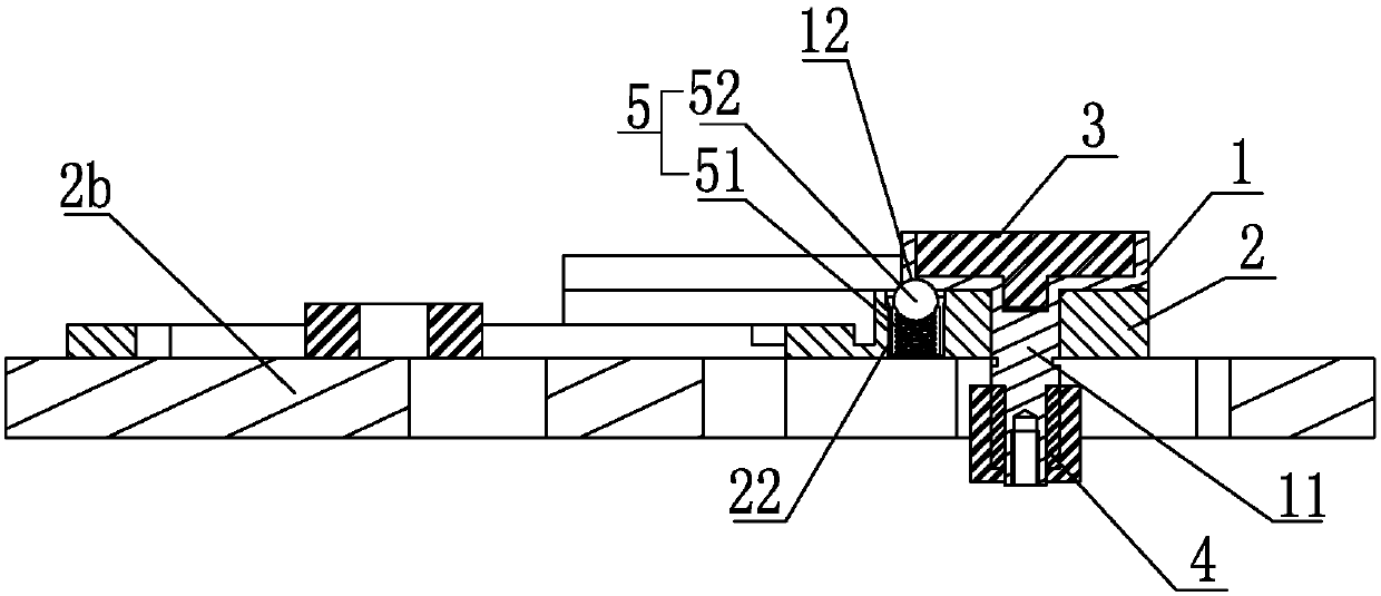
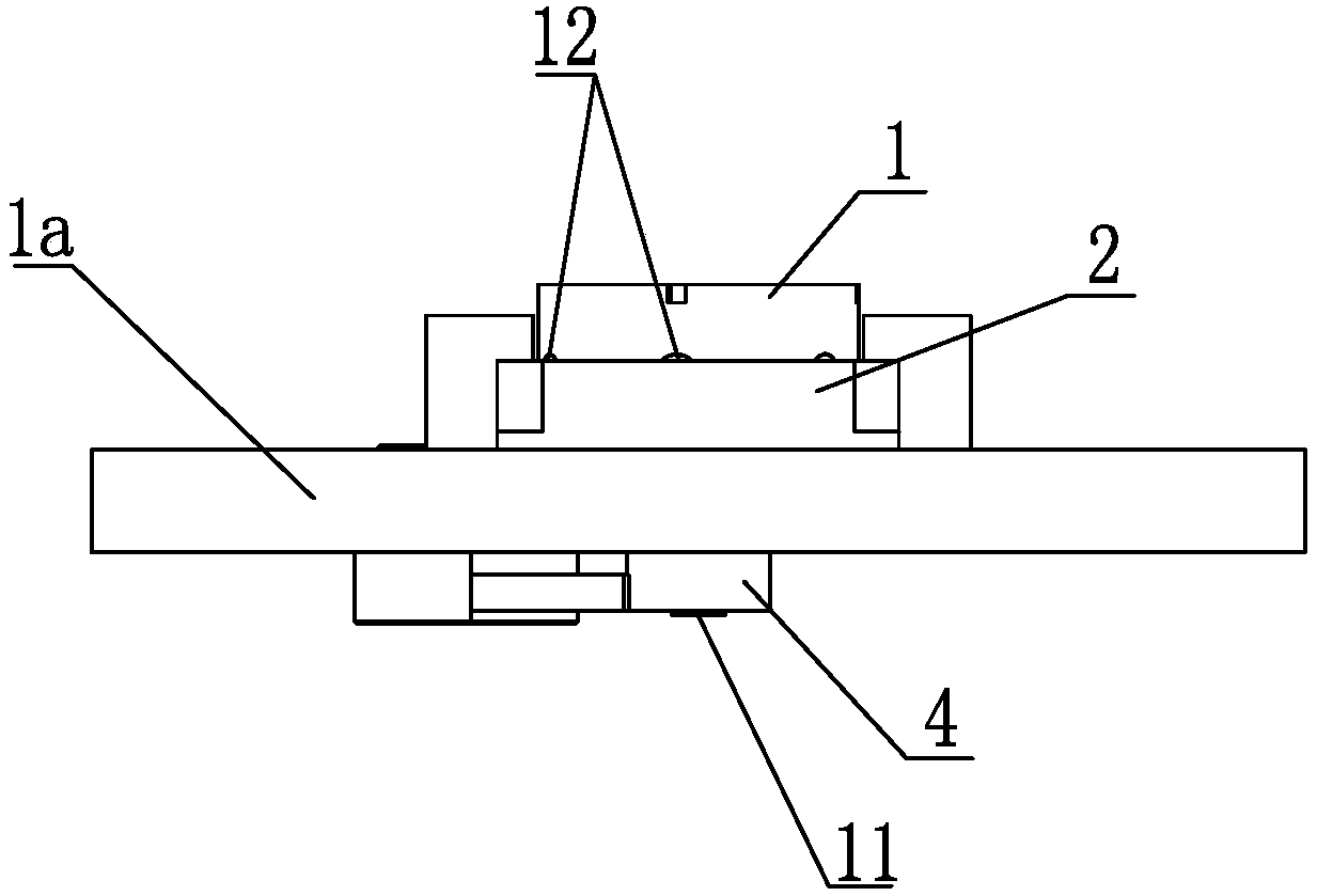
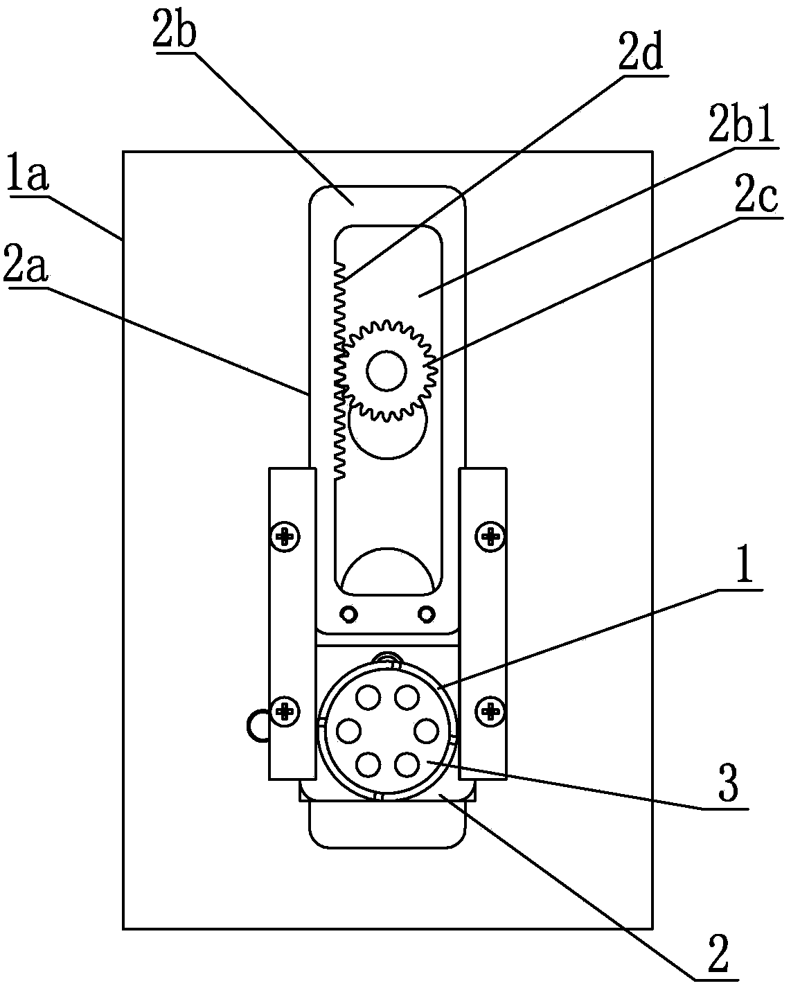
[0047] Such as figure 1 and Figure 25 As shown, a knife shim mechanism includes a rotatable knife shim device a, which is rotatably positioned on the positioning seat 2, and the rotatable knife shim device a is provided with a one-way bearing 4.

[0048] One-way bearing 4 is provided with driving lever 6 or rotating gear 9 that drives it to rotate.

[0049] It also includes a toggle device b positioned correspondingly to the toggle one-way bearing 4, and a clutch device c for clutch switching is provided between the toggle device b and the rotary knife shim device a.

[0050] The rotatable knife shim device a is provided with a centering shaft 11, which is rotatably positioned on the positioning seat 2 through the centering shaft 11, and the one-way bearing 4 is sleeved on the rotatable seat 1 or the centering shaft 11, and the one-way bearing 4 is A rotating gear 9 is provided.

[0051] The rotatable knife shim device a is provided with a centering shaft 11, which is rota...


PUM


Abstract

The invention relates to a cutter pad mechanism. The cutter pad mechanism comprises a rotary cutter pad device which is rotationally positioned on a positioning base, and a one-way bearing is arranged on the rotary cutter pad device. The cutter pad mechanism capable of being stirred in one direction to rotate and a bookbinding machine provided by the invention can automatically drive a drilling cutter base plate to rotate along the axis so as to adjust the position of the drilling cutter base plate relative to a drilling cutter, and the portion, drilled and destroyed by the drilling cutter, of the drilling cutter base plate is transferred, so that convenient adjustment is achieved, and the service life of a cutter pad is prolonged as much as possible.

Description

technical field [0001] The invention relates to a binding machine for binding office financial data, in particular to a knife shim mechanism of the binding machine. Background technique [0002] The base of the punching and binding machine is equipped with a drilling pad to ensure that the last piece of paper at the bottom can be effectively pierced and at the same time protect the edge of the drill from damage. Including the cutter pads of traditional manual and electric control binding machines, after being drilled by the knife edge at the same position, it will need to be replaced after the drill is damaged or the rubber pad is drilled through, which increases some unnecessary costs. On this basis, the turntable type shim invented by the applicant can manually rotate the angle of the shim to adjust the angle of the shim, and shift the position of the shim damaged by the drill bit to achieve convenient adjustment and increase the service life of the shim as much as possibl...

Claims


Application Information

Patent Timeline
Patent Type & Authority Patents(China)
IPC IPC(8): B42B5/02
CPCB42B5/02
Inventor 孙兵
Owner DELI GROUP CO LTD
Learn More