Cleaning cycle determining method of solar photovoltaic assembly

A solar photovoltaic, cleaning cycle technology, applied in the field of solar energy, to achieve the effect of improving resource waste and simple operation

Active Publication Date: 2016-04-20
CSG PVTECH +1
View PDF4 Cites 7 Cited by
  • Summary
  • Abstract
  • Description
  • Claims
  • Application Information

AI Technical Summary

Problems solved by technology

[0004] Based on this, it is necessary to provide a method for measuring the cleaning cycle of solar photovoltaic modules, so that cleaners can simply judge whether solar photovoltaic modules need to be cleaned, so that solar photovoltaic modules can be cleaned in time, and effectively improve the problem of waste of resources

Method used


Image

  • Cleaning cycle determining method of solar photovoltaic assembly
  • Cleaning cycle determining method of solar photovoltaic assembly
  • Cleaning cycle determining method of solar photovoltaic assembly

Examples


Embodiment 1

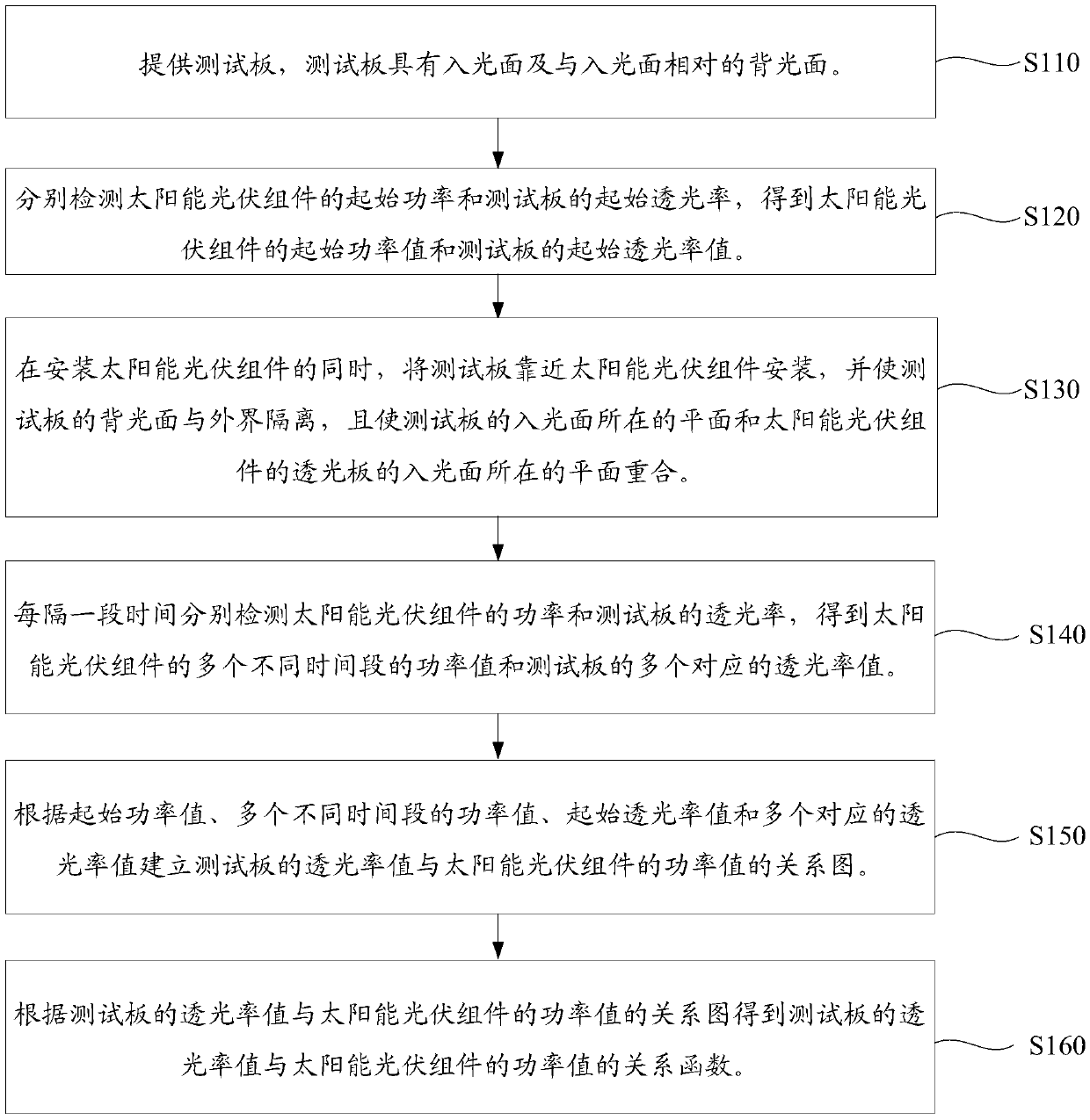
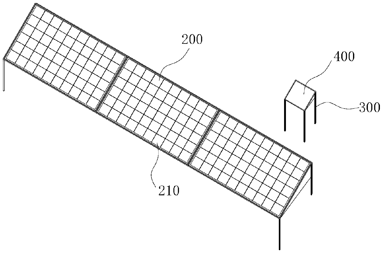
[0056] The specific process of the assay method of the cleaning cycle of the solar photovoltaic module of the present embodiment is as follows:

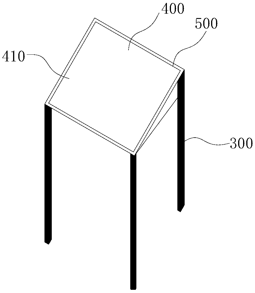
[0057] (1) The test board is prepared according to the preparation process of the light-transmitting plate of the solar photovoltaic module, wherein both the light-transmitting plate and the test plate are glass substrates.

[0058] (2) Set the second frame around the edge of the test board on the test board. The materials of the second frame and the first frame around the edge of the solar photovoltaic module are both aluminum, and the second frame is higher than the entrance of the test board. The height from one side of the light surface to the light-incident surface of the test board is equal to the height from the side of the first frame higher than the light-incident surface of the light-transmitting plate of the solar photovoltaic module to the light-incident surface of the light-transmitting plate, and the height of the second...

Embodiment 2

[0069] The specific process of the assay method of the cleaning cycle of the solar photovoltaic module of the present embodiment is as follows:

[0070] (1) The test board is prepared according to the preparation process of the light-transmitting plate of the solar photovoltaic module, wherein both the light-transmitting plate and the test plate are glass substrates.

[0071] (2) Set the second frame around the edge of the test board on the test board. The materials of the second frame and the first frame around the edge of the solar photovoltaic module are both aluminum, and the second frame is higher than the entrance of the test board. The height from one side of the light surface to the light-incident surface of the test board is equal to the height from the side of the first frame higher than the light-incident surface of the light-transmitting plate of the solar photovoltaic module to the light-incident surface of the light-transmitting plate, and the height of the second...


PUM


Abstract

The invention relates to a cleaning cycle determining method of a solar photovoltaic assembly. The determining method comprises the following steps of respectively performing detection to obtain an initial power value of the solar photovoltaic assembly and an initial light transmission rate value of a test board; when installing the solar photovoltaic assembly, installing the test board in a way of being near the solar photovoltaic assembly; isolating the shady surface of the test board from the outside; enabling a plane at which the light incident surface of the test board is located to be coincident with a plane at which the light incident surface of the light transmission plate of the solar photovoltaic assembly is located; respectively performing detection every a period of time to obtain power values of the solar photovoltaic assembly in a plurality of different time periods and a plurality of corresponding light transmission rate values of the test board; building a relationship diagram between the light transmission rate values of the test board and the power values of the solar photovoltaic assembly; obtaining a relationship function between the light transmission rate values of the test board and the power values of the solar photovoltaic assembly according to the relationship diagram. According to the relationship function, a cleaner can simply judge whether the solar photovoltaic assembly needs to be cleaned or not.

Description

technical field [0001] The invention relates to the field of solar energy, in particular to a method for measuring the cleaning period of a solar photovoltaic module. Background technique [0002] Solar power generation is a clean and green renewable energy. Under the background of the depletion of traditional energy sources and the increasing environmental pollution, solar power generation is more and more popular among people. However, since solar photovoltaic modules are usually installed outdoors, dust is easy to accumulate on the light-transmitting plate on the surface, and dust accumulation on the light-transmitting plate will seriously affect the utilization of light by the solar panels of the solar photovoltaic module, thereby reducing power generation. , Therefore, it is urgent to solve the influence of dust accumulation of solar photovoltaic modules on power generation. [0003] In order to solve the above problems, the traditional method is to directly cover some...

Claims


Application Information

Patent Timeline
Patent Type & Authority Applications(China)
IPC IPC(8): G01R31/26H02S50/10H02S40/10
CPCH02S40/00H02S50/00Y02B10/10Y02E10/50
Inventor 罗飞张清春孔国寿龚露叶雄新孙小菩彭华
Owner CSG PVTECH
Why Eureka
Try Eureka