
System architecture construction method

A system architecture and construction method technology, applied in the field of systems engineering, can solve problems such as connection difficulties, unusable models, and difficulties in getting started, and achieve the effect of avoiding incomplete considerations.

Active Publication Date: 2016-04-20
XIAN AIRCRAFT DESIGN INST OF AVIATION IND OF CHINA
View PDF3 Cites 1 Cited by
  • Summary
  • Abstract
  • Description
  • Claims
  • Application Information

AI Technical Summary

Problems solved by technology

Both UML and SysML analyze the system from multiple perspectives through different model diagrams. First, the system is regarded as a black box, starting from the external relationship, multi-dimensional analysis of the system, and finally the system is transformed from a black box to a white box for forward design. , this design method analyzes the system from the perspectives of system boundaries, external stakeholders, status, etc. This kind of analysis is relatively comprehensive, and it is not easy to miss requirements, especially when the user requirements in the early stage are not very clear, the system architecture can be obtained through layer-by-layer analysis , the disadvantage is that it is difficult to get started and requires professional training. For the multi-person collaborative work mode of complex systems, multiple people draw multiple system models for the same system. Even if the system model design standard is customized, there is still poor matching between the models. , Difficulty in docking, unusable models, etc.

Method used


Image

  • System architecture construction method
  • System architecture construction method
  • System architecture construction method

Examples


Embodiment 1

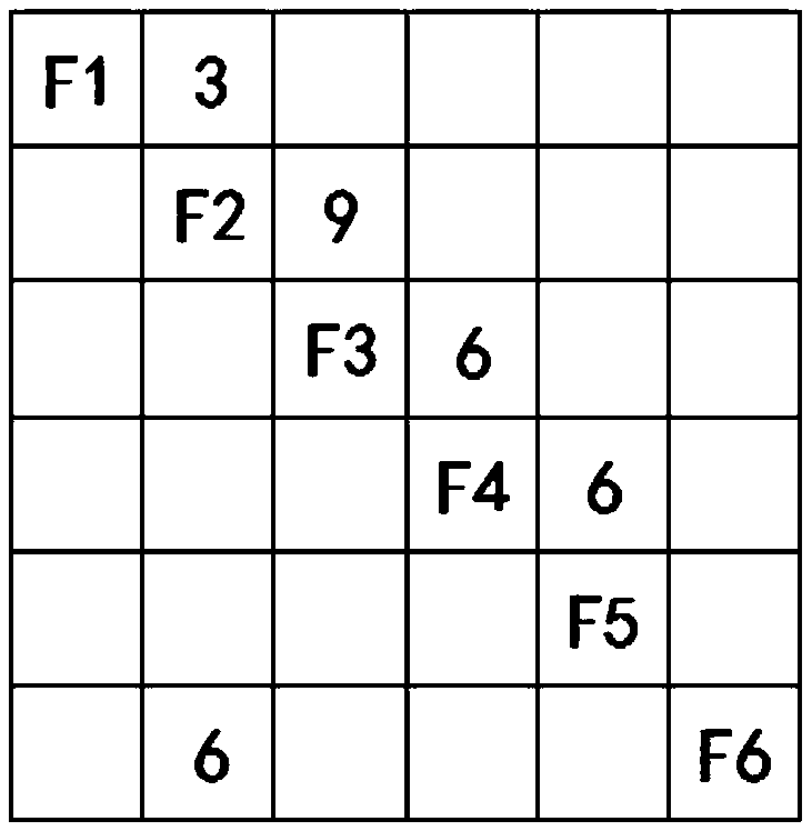
[0038] Taking the flight control system as an example, the controlled object is the rudder surface, which needs to realize the six functions of "sensing the driving command, D / A conversion, calculation, A / D conversion, driving the movement of the actuator and sensitive rudder surface position". The data relationship between them, drawing the EFFBD diagram of the system is as follows figure 1 As shown, among them, F1 represents the perceived driving command, F2 represents the D / A conversion, F3 represents the calculation, F4 represents the A / D conversion, F5 represents the movement of the driving actuator, and F6 represents the position of the sensitive control surface. figure 1 It can be seen that the premise of F1 realization is that the driver manipulates the steering column and the driver manipulates the pedals, the output of which is longitudinal driving displacement signal, lateral driving displacement signal, etc., and the output of F1 is used as the input of F2, and the ...

Embodiment 2

[0052] Similar to Embodiment 1, take the mobile phone to answer the phone as an example. When making a call, the mobile phone needs to have a signal, so it has the function of receiving the operator's signal. In addition, it should also have the function of unlocking the mobile phone, inputting the other party's number, calling the mobile phone to store contacts, and making a call. The function of receiving missed calls and storing them. Take this as an example, specifically as Figure 4 shown.

[0053] first N 2 The construction of the graph will not be described in detail, and then the architecture allocation table is constructed, as shown in Table 3.

[0054] Table 3. Architecture Allocation Table

[0055]

[0056]

[0057] According to the architecture allocation table, it is found that F4, F5, F7, and F8 are all completed by the handset, microphone, memory, and mobile phone chip. F3 and F6 are all implemented by software. One function, and the unlocking function...

Embodiment 3

[0060] Similar to the above embodiment, the main steps are as follows:

[0061]First select the necessary functional requirements for system design from the functional requirements of the system; then draw the system EFFBD diagram according to the necessary functional requirements of the system, and draw the interface relationship between functions in EFFBD combined with the interface requirements. The EFFBD diagram is a functional block diagram drawn in time series of functional occurrences. The functional block diagram is represented by a box plus a serial number, and the data flow between functions is represented by a rounded rectangle plus an arrow. A single arrow represents data flow, and a double arrow represents trigger data, that is, only when the data occurs, the function can be executed. . If there are multiple functions, the function flow chart can also expand the functions of the system, sub-system and subsystem in a hierarchical manner;

[0062] Second, draw the...


PUM


Abstract

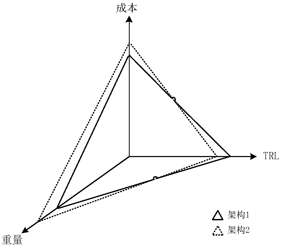
The invention discloses a system architecture construction method and belongs to the field of system engineering. On the basis of an N2 diagram of a system architecture, an architecture allocation sheet is constructed, the allocation condition of multiple physical devices in any architecture scheme is represented, then all physical interface relations of the physical devices in the architecture allocation sheet when the physical device realizes corresponding functions are listed, and a second N2 diagram with physical interface relations is constructed according to the physical interface relations; finally, multiple architecture schemes with the physical interface relation similarity up to the threshold under different architecture schemes are found out from the second N2 diagram, the same physical device with different indexes under the multiple architecture schemes is found out from the architecture allocation sheet, a spider diagram of the physical device is constructed, and the optimal system architecture scheme is selected according to the spider diagram. With the adoption of the method, the functional requirement of the system is unfolded in a hierarchy form, ordinal relations and data streams among functions are displayed, and the optimal architecture scheme can be selected.

Description

technical field [0001] The invention belongs to the field of system engineering, and in particular relates to a method for constructing a system architecture. Background technique [0002] The system architecture is to realize the technical framework of the determined requirements, make a plan, and use a complete set of complete tools to complete the task in the planned steps. [0003] In the prior art, system engineering methodology and related tools are generally used for architecture design, such as UML or SysML visualization tools, to analyze and describe the system from different perspectives, for example, UML uses use case diagrams to describe system functions from the perspective of users, which is A model diagram of system functionality as observed by the user. A class diagram describes the static structure of classes in the system. The sequence diagram represents the dynamic cooperative relationship between objects, emphasizes the order in which messages are sent ...

Claims


Application Information

Patent Timeline
Patent Type & Authority Applications(China)
IPC IPC(8): G06F17/50
CPCG06F30/00G06F2111/04
Inventor 黎娜
Owner XIAN AIRCRAFT DESIGN INST OF AVIATION IND OF CHINA
Learn More