
Magnetic core and circuit board using magnetic core

A circuit board and magnetic core technology, which is applied in the direction of printed circuits connected with non-printed electrical components, transformer/inductor magnetic cores, etc. Large effective working area, reasonable structure layout and design, solving the effect of coil magnetic field line divergence

Inactive Publication Date: 2014-08-13
ANHUI HUALIN MAGNETIC TECH
View PDF0 Cites 0 Cited by
  • Summary
  • Abstract
  • Description
  • Claims
  • Application Information

AI Technical Summary

Problems solved by technology

[0004] Aiming at the problems existing in the prior art, the present invention proposes a magnetic core, which has a reasonable structural layout, large effective working area, high space utilization rate, solves the problem of divergence of the magnetic induction lines of the coil at the root of the winding post, and improves The stability and reliability of the electromagnetic characteristics of the magnetic core

Method used


Image

  • Magnetic core and circuit board using magnetic core
  • Magnetic core and circuit board using magnetic core
  • Magnetic core and circuit board using magnetic core

Examples


Embodiment Construction

[0017] The technical scheme of the present invention will be further described below in conjunction with the accompanying drawings and through specific embodiments:

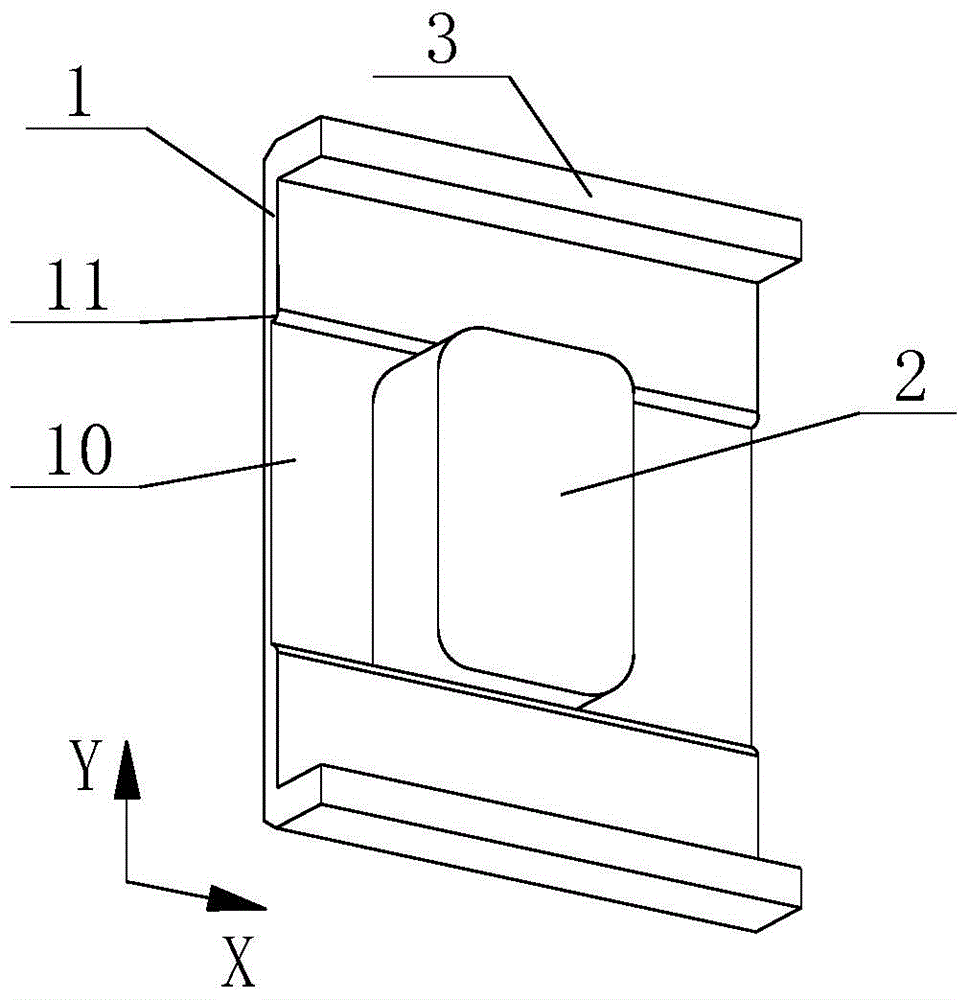
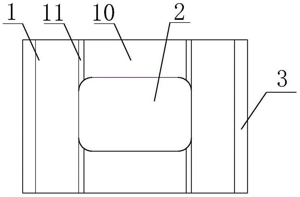
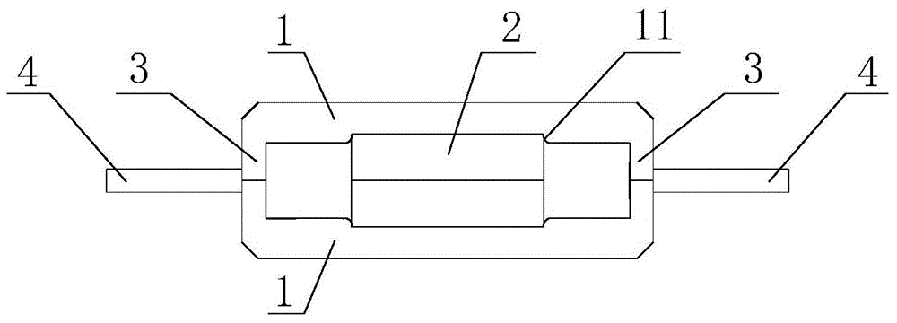
[0018] Such as Figures 1 to 3 as shown, figure 1 It is a structural schematic diagram of a magnetic core proposed by the present invention, figure 2 for figure 1 Front view of the proposed magnetic core, image 3 for figure 1 A side view of the proposed core mounted to a circuit board.

[0019] refer to figure 1 and 2 , a magnetic core proposed by the present invention is composed of a bottom plate 1, two side plates 2 and a winding post 3;

[0020] The shape of the bottom plate 1 and the side plate 2 is rectangular, and the winding post 3 is a cuboid. The two side plates 2 are arranged on both sides of the length direction of the bottom plate 1 and are perpendicular to the bottom plate 1. The width D2 of the bottom plate 1 is the same as the length C1 of the two side plates 2. Equal, the winding post 3...


PUM


Abstract

The invention discloses a magnetic core. The magnetic core consists of a bottom plate, two side plates and a winding post, wherein the two side plates are arranged on the two sides in the length direction of the bottom plate and are vertical to the bottom plate; the width of the bottom plate is equal to the length of the two side plates; the winding post is arranged on the middle part of the bottom plate; the length direction of the winding post is consistent to that of the bottom plate; the distance L1 from the two sides of the width direction of the winding post to the two side plates is greater than the distance L2 from the two sides of the length direction of the winding post to the two side plates; the length R1 of the winding post is greater than L1; the width R2 of the winding post is greater than L2; two grooves are formed in the bottom plate from the two sides of the length direction of the winding post to the two sides of the bottom plate in an extending way; the side ridges of the winding post are in smooth transition; the height of the two side plates is equal to that of the winding post. The magnetic core provided by the invention is reasonable in structural layout, the problem that coil magnetic induction wires at the root of the winding post scatter is solved, and meanwhile, the stability and the reliability of electromagnetic characteristics of the magnetic core are improved. The invention also provides a circuit board using the magnetic core.

Description

technical field [0001] The invention relates to the technical field of magnetic cores, in particular to a magnetic core and a circuit board using the magnetic core. Background technique [0002] The magnetic core is a sintered magnetic metal oxide composed of various iron oxide mixtures. In the prior art, ferrite magnetic cores are used in coils and transformers of various electronic devices. For example, manganese-zinc ferrite and nickel-zinc ferrite are typical magnetic core materials. Among them, manganese-zinc ferrite has the characteristics of high magnetic permeability and high magnetic flux density, and has a relatively high magnetic flux density when the frequency is lower than 1MHz. Low loss characteristics, nickel-zinc ferrite has extremely high resistivity, low magnetic permeability of less than a few hundred, and low loss at frequencies higher than 1MHz. [0003] The material and structure of the magnetic core are important factors affecting the performance of t...

Claims


Application Information

Patent Timeline
IPC IPC(8): H01F27/24H05K1/18
Inventor 沈宏江
Owner ANHUI HUALIN MAGNETIC TECH
Learn More