A Magnetic Ring Optimal Combination Method for Suppressing Electromagnetic Scattering
A technology of electromagnetic scattering and combination method, applied in the installation of cables, electrical components, overhead installation, etc., can solve the problems of increasing the power loss of the line, reducing the initial permeability, affecting the lightning protection design of the line, and suppressing the induced current. , The effect of suppressing electromagnetic scattering and induced current distribution
Active Publication Date: 2018-07-20
CHINA ELECTRIC POWER RES INST +1
View PDF5 Cites 0 Cited by
- Summary
- Abstract
- Description
- Claims
- Application Information
AI Technical Summary
Problems solved by technology
But this method has the following disadvantages: 1. Increase the power loss of the line; 2. It affects the lightning protection design of the line; 3. It may not have the expected effect on the electromagnetic waves that need to be suppressed.
Although the magnetic ring is installed and fixed on the wire, there is still an inevitable air gap between the two semicircles, and the air gap will reduce the initial magnetic permeability
Method used
View moreImage
Smart ImageViewing Examples
Examples
Embodiment
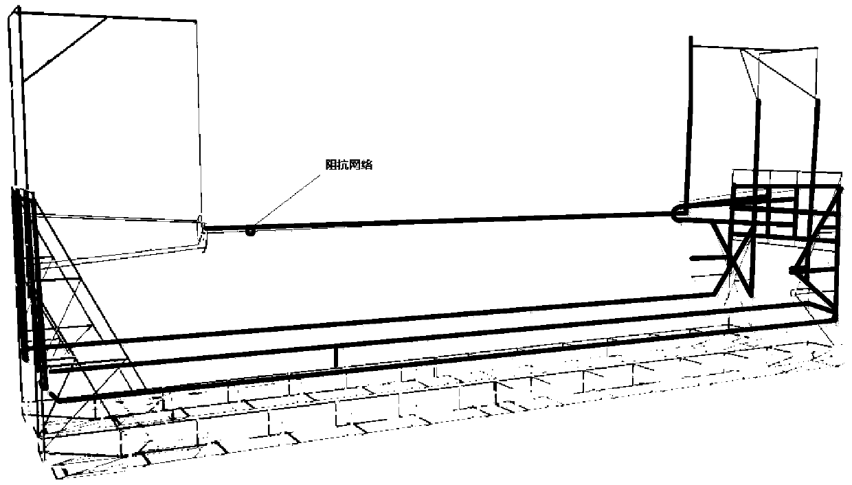
[0125] In order to verify the effectiveness of electromagnetic scattering suppression by the series magnetic rings of overhead transmission lines, the electromagnetic scattering test of the series magnetic rings of overhead lines was carried out. The simulation test is as follows: image 3 shown;
Login to View More PUM
 Abstract
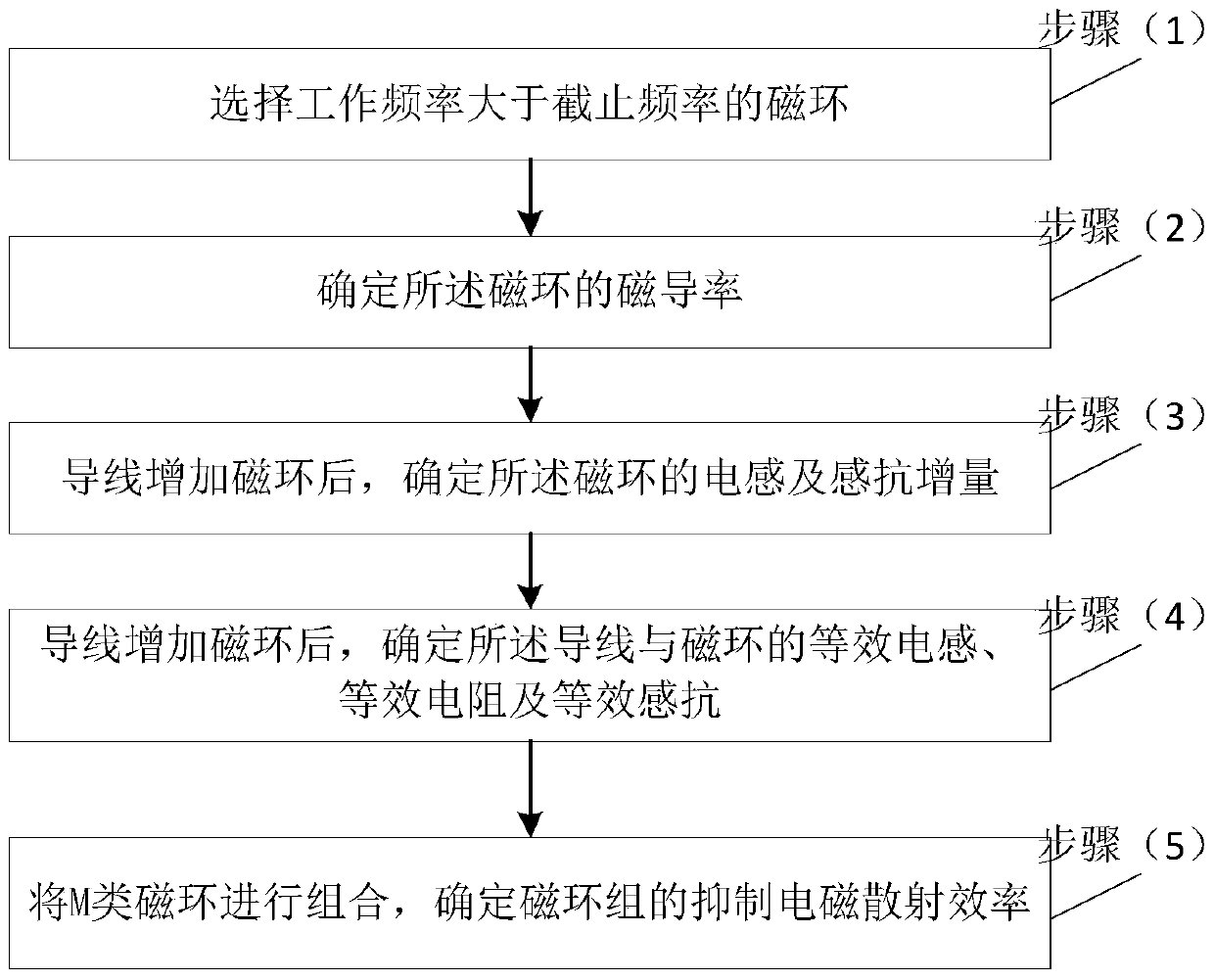
The invention relates to a magnet ring optimization combination method for suppressing electromagnetic scattering. The method comprises: (1), a magnetic ring with a working frequency larger than a cut-off frequency is selected; (2), the magnetic permeability of the magnetic ring is determined; (3), after the magnetic ring is added to the lead, inductance and inductive reactance increments of the magnetic ring are determined; (4), after adding of the magnetic ring to the lead, an equivalent inductance, an equivalent resistance and an equivalent inductive reactance of the lead and the magnetic ring are determined; and (5), M types of magnetic rings are combined and an electromagnetic scattering suppressing efficiency of the magnetic ring is determined. According to the method, the induced current on the high-voltage overhead power transmission line can be reduced by loading a ferrite magnet ring at a specific area of the power transmission line, so that the electromagnetic scattering generated by the power transmission line can be suppressed from the source.
Description
technical field [0001] The invention relates to the field of electromagnetic compatibility of high-voltage power transmission and transformation engineering, in particular to a magnetic ring optimization combination method for suppressing electromagnetic scattering. Background technique [0002] The electromagnetic scattering formed by the high-voltage overhead transmission line to the radio station mainly comes from the induced current generated by the high-voltage overhead wire and the iron tower excited by the electromagnetic field of the radio signal. This induced current radiates electromagnetic waves to the space through the metal structure, and the radiated electromagnetic waves are at the same frequency as the source signal. Interference will change the amplitude and phase of the original radio signal. [0003] Regarding the method of reducing the electromagnetic scattering of transmission lines, the current domestic and foreign solutions to electromagnetic scatterin...
Claims
Login to View More Application Information
Patent Timeline
 Patent Type & Authority Patents(China)
IPC IPC(8): H02G7/00
CPCH02G7/00
Inventor 干喆渊万保权刘震寰赵军周兵陈豫朝路遥张斌李东云
Owner CHINA ELECTRIC POWER RES INST
Features
- R&D
- Intellectual Property
- Life Sciences
- Materials
- Tech Scout
- Unparalleled Data Quality
- Higher Quality Content
- 60% Fewer Hallucinations
Learn More Browse by: Latest US Patents, China's latest patents, Technical Efficacy Thesaurus, Application Domain, Technology Topic, Popular Technical Reports.
© 2025 PatSnap. All rights reserved.Legal|Privacy policy|Modern Slavery Act Transparency Statement|Sitemap|About US| Contact US: help@patsnap.com


