Automatic gain control circuit for receivers

An automatic gain control and receiver technology, applied in the field of signal processing, can solve the problems of slow amplitude stabilization, complicated circuits, and inability to monitor the input signal spectrum in real time, and achieve the effect of fast amplitude stabilization.

Active Publication Date: 2016-04-20
THE 41ST INST OF CHINA ELECTRONICS TECH GRP
View PDF7 Cites 25 Cited by
  • Summary
  • Abstract
  • Description
  • Claims
  • Application Information

AI Technical Summary

Problems solved by technology

[0064] The purpose of the present invention is to solve the problems of poor adaptability, poor working stability, complicated circuit and slow speed of amplitude stabilization for the automatic gain control circuit in the existing receiver. , the lack of real-time monitoring of the spectrum of the input signal, a receiver automatic gain control circuit with a spectrum monitoring function, high precision, simple circuit, and fast amplitude stabilization is proposed

Method used


Image

  • Automatic gain control circuit for receivers
  • Automatic gain control circuit for receivers
  • Automatic gain control circuit for receivers

Examples


Embodiment Construction

[0109] The specific embodiment of the present invention will be further described below in conjunction with accompanying drawing and specific embodiment:

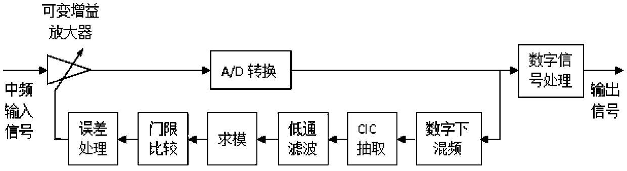
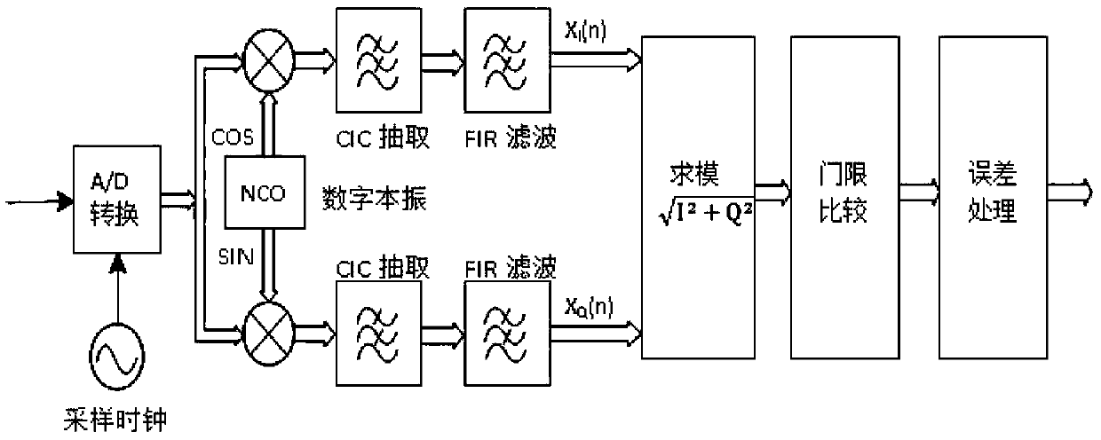
[0110] Such as Figure 8-9 As shown, a receiver automatic gain control circuit includes a variable gain amplifier, the output of the variable gain amplifier is connected to an analog-to-digital converter, and the output of the analog-to-digital converter is connected to a digital signal processor, an automatic gain control loop and Spectrum analysis unit, the signal output by the analog-to-digital converter is divided into three parts, one part enters the digital signal processor, and the other two parts respectively enter the automatic gain control loop and the spectrum analysis unit; the automatic gain control loop includes sequentially connected signal absolute Value circuit, adaptive equalizer, maximum value circuit, threshold comparison circuit and error processing circuit, the signal in the automatic gain control loop...


PUM


Abstract

The invention relates to an automatic gain control circuit for receivers, and in particular to the technical field of signal processing. The circuit is used for solving the problems that an analog-type automatic gain control circuit for the receivers is poor in adaptability, work stability and amplitude stabling accuracy, an existing digital automatic gain control circuit for the receivers is complex and low in amplitude stabling speed and the spectrum of input signals cannot be monitored in real time. The automatic gain control circuit for the receivers comprises a variable gain amplifier, wherein the output end of the variable gain amplifier is connected with an analog-digital converter; the output end of the analog-digital converter is connected with a digital signal processor, an automatic gain control loop and a spectrum analyzing unit; the signal output by the analog-digital converter is divided into three parts, one part enters the digital signal processor and the other two parts respectively enter the automatic gain control loop and the spectrum analyzing unit; and the automatic gain control loop comprises a request signal absolute value circuit, an adaptive equalizer, a maximizing circuit, a threshold comparison circuit and an error processing circuit which are sequentially connected.

Description

technical field [0001] The invention belongs to the technical field of signal processing, and in particular relates to a receiver automatic gain control circuit. Background technique [0002] The automatic gain control circuit is an important circuit essential in the receiver. The receiver input signal is usually a weak signal, and its dynamic range is very wide. To process the input radio frequency signal, an automatic gain control circuit is necessary. The function of the automatic gain control circuit is to appropriately amplify the input weak signal, and appropriately attenuate the input larger signal, and adapt the signal to an appropriate level, so that subsequent signal processing can be performed. [0003] The block diagram of the receiver circuit using analog automatic gain control is as follows: figure 1 shown. The input RF signal is amplified by a variable gain amplifier, and then passes through a directional coupler to couple a small part of the energy of the ...

Claims


Application Information

Patent Timeline
Patent Type & Authority Applications(China)
IPC IPC(8): H04B1/16H03G3/30
CPCH03G3/30H04B1/16
Inventor 张则乐胡林军
Owner THE 41ST INST OF CHINA ELECTRONICS TECH GRP
Why Eureka
Try Eureka