Monitoring device for loom, loom and monitoring method

A technology for monitoring devices and looms, applied in looms, auxiliary weaving equipment, textiles, etc., can solve the problems that textile defects cannot be detected, and the time between the first appearance and the detection of the same defect is difficult to detect, etc., to achieve high precision effects

Active Publication Date: 2018-12-04
STAUBLI SARGANS AG
View PDF10 Cites 1 Cited by
  • Summary
  • Abstract
  • Description
  • Claims
  • Application Information

AI Technical Summary

Problems solved by technology

However, due to the mode of operation of the device described there, there is a general problem that a textile defect is not detected until several centimeters of material have been woven between the time it first appears and when the same defect is detected again the defect
Additionally, some textile defects cannot or are difficult to detect

Method used


Image

  • Monitoring device for loom, loom and monitoring method
  • Monitoring device for loom, loom and monitoring method
  • Monitoring device for loom, loom and monitoring method

Examples


Embodiment Construction

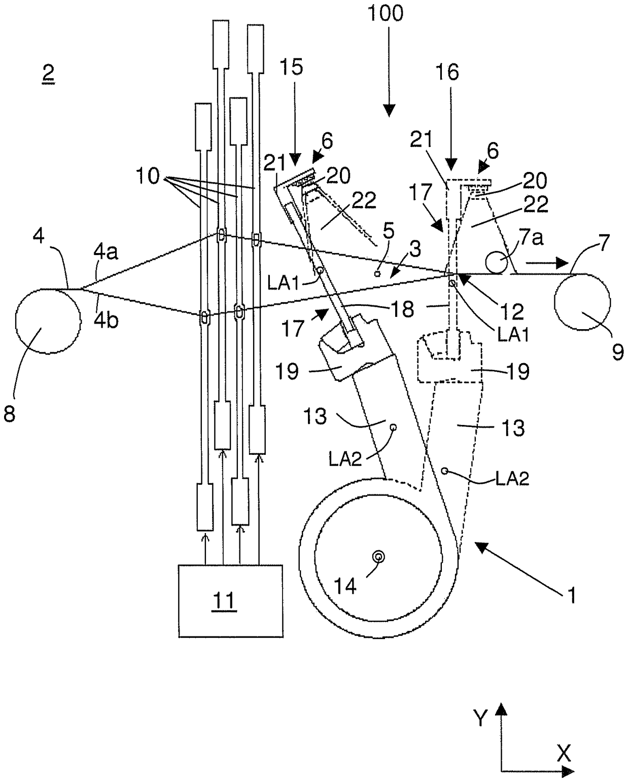
[0079] figure 1 shows a first exemplary embodiment of a monitoring device for a loom 2 in combination with a weft thread beating device 1 . The weaving machine 2 is shown only schematically, wherein the figure emphasizes the fabric-forming region 3 formed by the warp threads 4 . According to the above proposal, the weft thread beating device 1 is additionally provided with a camera device 6 for detecting the warp thread 4 and the weft thread 5 to be woven or the woven fabric 7, which will be explained in more detail later.

[0080] In this regard, refer to Figure 1-3 The shown coordinate system with coordinate axes X, Y and Z assumes that the direction of the weft thread 5 (weft direction) extends along the coordinate axis Z and that the fabric 7 is arranged parallel to the plane formed by the coordinate axes X and Z.

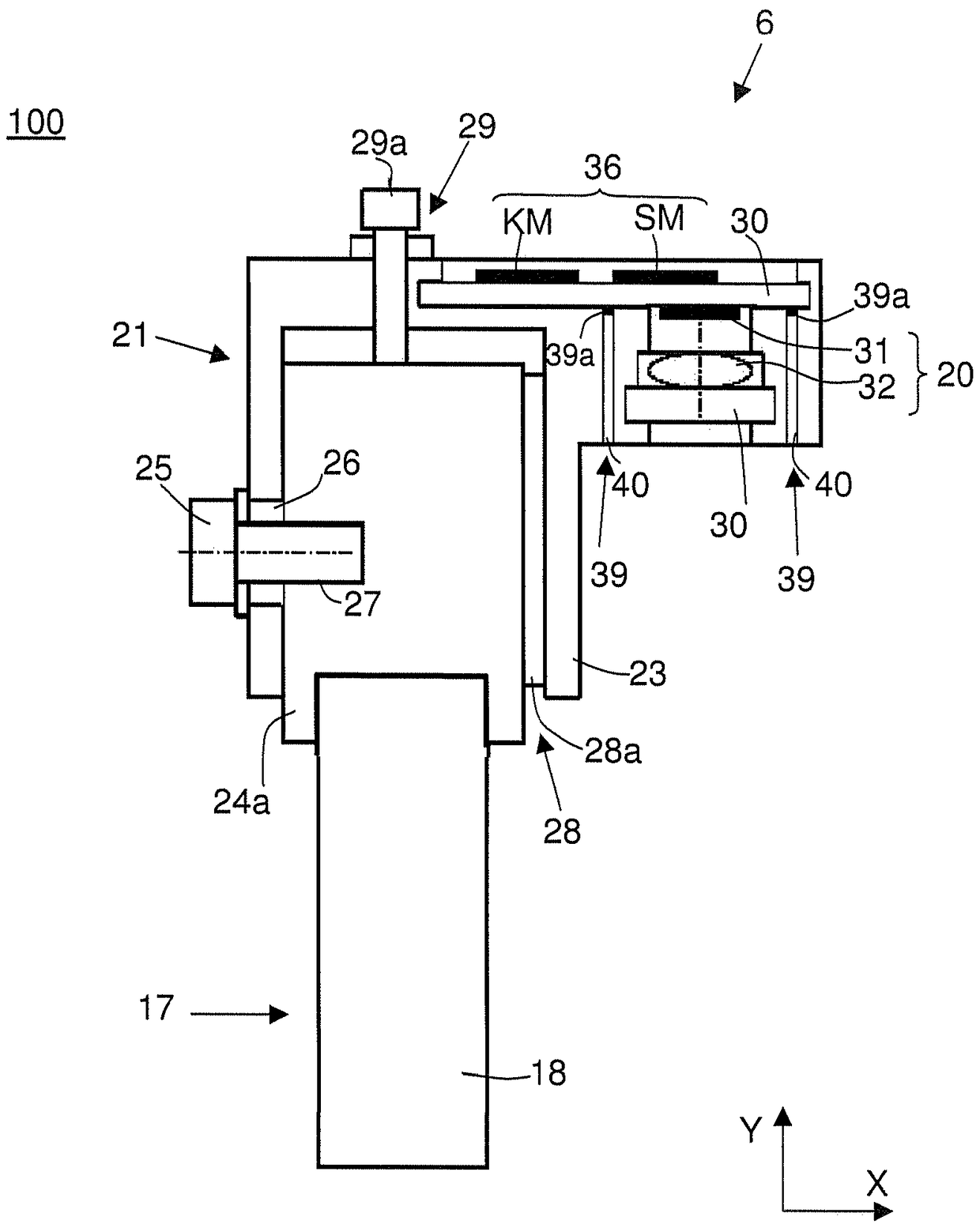
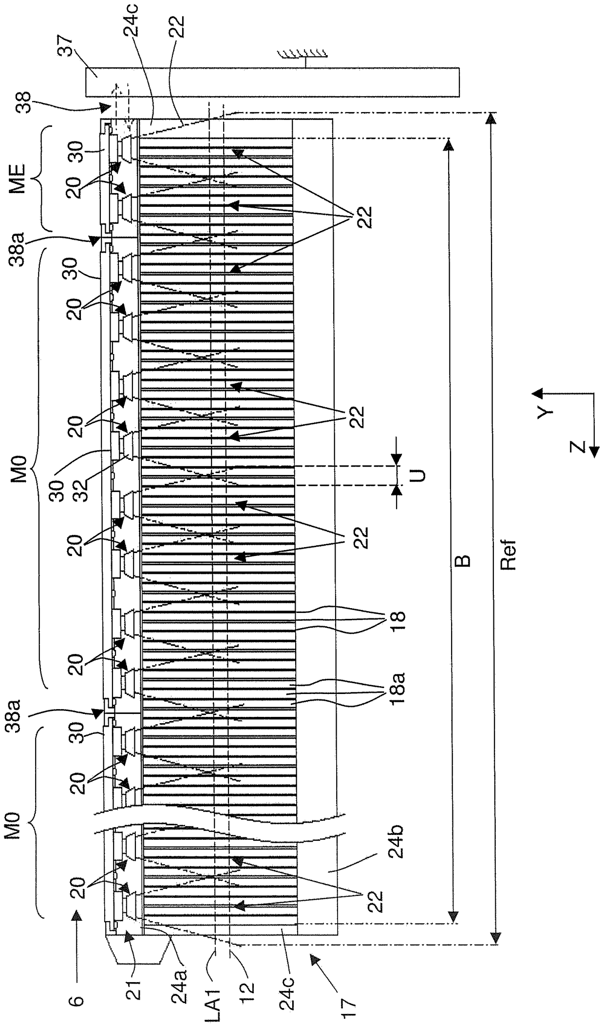
[0081] The camera arrangement 6 may comprise one or more camera devices 20 configured to record images. In the above example, the camera arrangement includ...


PUM


Abstract

A monitoring device (100) for a loom (2), comprising at least one camera device (20) and a weft yarn beating device (1), wherein the weft yarn beating device (1) comprises at least one reed ( 13) and / or the sley (17), and the reed (17) and / or the sley (13) extend along the longitudinal direction (LA1, LA2) of the weft thread beating device (1). At least one camera device (20) is fixed to the weft thread beating-up device (1) and comprises a plurality of sensor elements arranged next to each other. The camera device (20) is designed to record images by means of sensor elements, wherein the sensor elements are arranged in a row extending approximately parallel to the longitudinal direction (LA1, LA2) of the weft thread beating-up device (1).

Description

technical field [0001] The invention relates to a monitoring device for a loom. Furthermore, the invention relates to a weaving machine with a monitoring device. The invention finally also relates to a method for monitoring the warp threads of a weaving machine. Background technique [0002] Today, automated looms are commonly used to produce textile materials. Such looms exist in various embodiments. The main difference lies, for example, in the way the weft threads are guided through the fabric forming zone. In this context, for example, weaving machines are known which use a shuttle to pass the weft thread through the fabric forming area. Weaving machines are also known in which the weft thread is passed through the fabric forming area by means of a gripper device. More recently, looms that utilize compressed air to pass the weft yarn through the fabric forming area have also been successfully used. [0003] Regardless of their exact construction, today's looms are ...

Claims


Application Information

Patent Timeline
Patent Type & Authority Patents(China)
IPC IPC(8): D03D49/62D03D51/20D03D51/34
CPCD03D49/62D03D51/20D03D51/34H04N23/54H04N23/66H04N23/90D03D49/00D03D51/00D03J1/005D03J1/007D03J1/24G06T7/0008G06T2207/30124H04N5/77H04N7/181
Inventor 马库斯·沃尔夫阿尔明·阿克曼
Owner STAUBLI SARGANS AG
Why Eureka
Try Eureka