
Servo pressure spot welding system

A technology of spot welding and welding tongs, which is applied in the field of servo pressurized spot welding system, can solve the problems that the welding pressure cannot change with the welding process, increase the cost of servo pressurization, etc., and achieve process upgrades, improve welding quality, and high precision Effect

Active Publication Date: 2018-12-28
天津七所高科技有限公司
View PDF9 Cites 0 Cited by
  • Summary
  • Abstract
  • Description
  • Claims
  • Application Information

AI Technical Summary

Problems solved by technology

In terms of welding pressure control, the current manual welding system cannot realize servo online automatic pressure control. The widely used servo robot welding system can control the welding pressure with servo drive, but there are some shortcomings as follows: First, the control of welding pressure It is carried out by the robot controller. If you want to achieve servo pressurization, you must use a servo robot with external axis control and an external axis motor, so the cost of servo pressurization is increased; second, the welding current and welding time are controlled by welding. The controller is used to control the welding pressure, while the welding pressure is controlled by the robot. The three cannot be controlled synchronously in the process sequence. At present, in order to ensure the stability of welding, the welding pressure can only be kept constant from the beginning of welding to the end of welding; 3. From the perspective of welding process, the welding pressure cannot be changed with the welding process, and the pressure can not be changed at any time during the welding process. For some special welding process materials, high-quality welding cannot be performed.

Method used


Image

  • Servo pressure spot welding system
  • Servo pressure spot welding system
  • Servo pressure spot welding system

Examples


Embodiment Construction

[0032] The specific implementation manners of the present invention will be briefly described below in conjunction with the accompanying drawings.

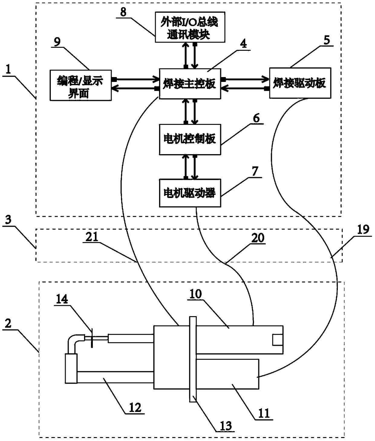
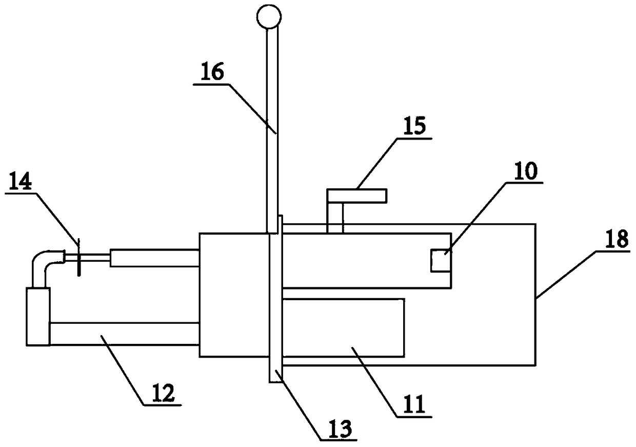
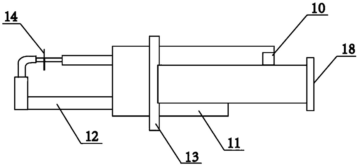
[0033] Such as figure 1 As shown, a servo pressurized spot welding system is characterized in that it includes a welding controller 1, a welding tongs 2 and a connecting cable 3, the welding controller 1 is connected to the welding tongs 2 through the connecting cable 3, and the welding control The device 1 includes a welding main control board 4, a welding driver board 5, a motor control board 6, a motor driver 7, an external I / O bus communication module 8 and a programming / display interface 9, and the welding tongs 2 includes a servo motor 10 and a transformer 11 , the electrode arm 12 and the welding tongs body 13, the connecting cable 3 includes a welding power line 19, a motor signal / power line 20, and a welding machine control line 21.

[0034] The main control board 4 of the welding machine takes the single-chip microcompu...


PUM


Abstract

The invention aims at providing a servo pressurizing spot welding system. The system comprises a welding controller, welding tongs and a connecting cable, wherein the welding controller is connected to the welding tongs through the connecting cable, and the welding controller comprises a welding main control panel, a welding driving board, a motor control board, a motor driver, a programming / display interface and an external I / O bus communication module; the welding tongs comprise a transformer, an electrode arm, a servo motor and a welding tongs body bracket; the connecting cable comprises a welding power wire, a welder control wire and a motor signal / power wire. The servo pressurizing spot welding system has the beneficial effects that the function of controlling the welding pressure can be achieved on the basis of a traditional welding controller, and the dependence of an current technology on robot servo control can be removed, so that the applicable scope of servo welding can be expanded, and the servo pressure control of manual welding tongs and automatic welding tongs can be achieved.

Description

technical field [0001] The invention relates to the technical field of welding devices, in particular to a servo pressure spot welding system. Background technique [0002] In the field of spot welding technology, there are three main factors affecting welding quality: welding current, welding time, and welding pressure. With the continuous development of the automobile industry, new materials and new processes are constantly being applied, and the control of welding current and welding pressure is becoming more and more important. The more stringent the requirements, the development from the power frequency 50Hz controller to the intermediate frequency controller has greatly improved the control accuracy and ensured the welding quality. In terms of welding pressure control, the current manual welding system cannot realize servo online automatic pressure control. The widely used servo robot welding system can control the welding pressure with servo drive, but there are some ...

Claims


Application Information

Patent Timeline
Patent Type & Authority Patents(China)
IPC IPC(8): B23K37/00
CPCB23K37/00
Inventor 胡敏洪涛龚蒙
Owner 天津七所高科技有限公司
Learn More