

A pin removal device and method of use thereof
A pin shaft and driving device technology, which is applied in metal processing, metal processing equipment, manufacturing tools, etc., can solve the problems of restricting the output and production efficiency of hydraulic supports, the hinge pin cannot be pulled out, and the hinge parts are corroded, so as to achieve practicability Strong, easy to move, and reduce work intensity
- Summary
- Abstract
- Description
- Claims
- Application Information
AI Technical Summary
Problems solved by technology
Method used
Image

Examples
Embodiment 1
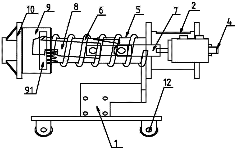
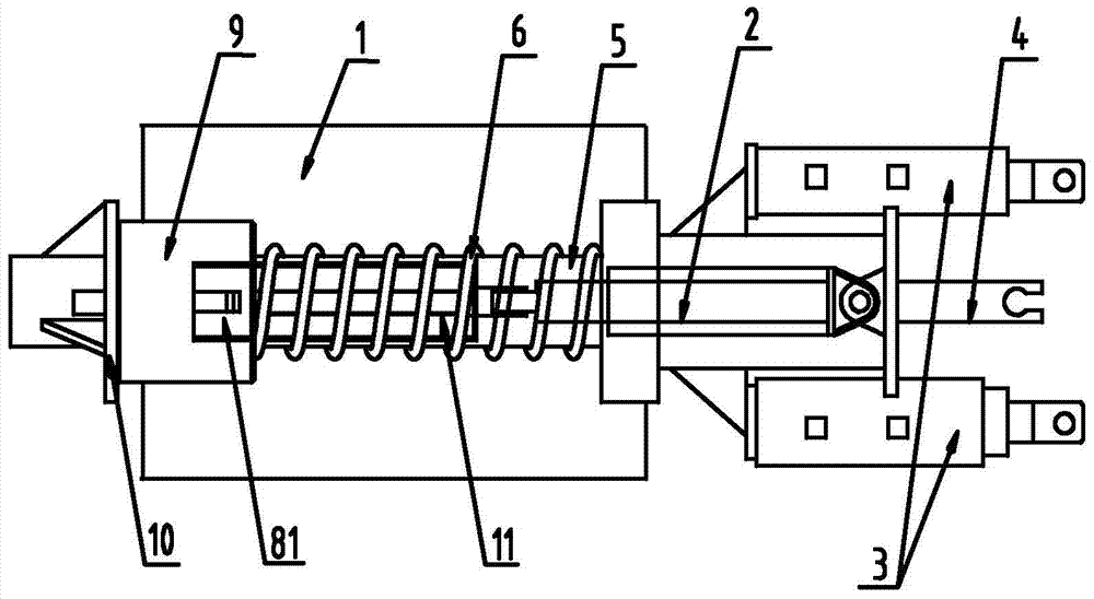
[0036] Such as figure 1 , figure 2 As shown, a pin removal device includes a support base 1, a main action part 2 and an auxiliary action part 3 located above the support base 1, the two sides of the main action part 2 are respectively provided with auxiliary action parts 3, and the The above-mentioned leading action part 2 and auxiliary action part 3 are arranged in antiparallel, reasonable in structure, reliable in operation, and high in safety factor. The work intensity of the operator is reduced, and the work efficiency is high. The sliding wheel 12 is arranged at the bottom of the support base 1, which can realize the position transfer of the whole device and is convenient to move.
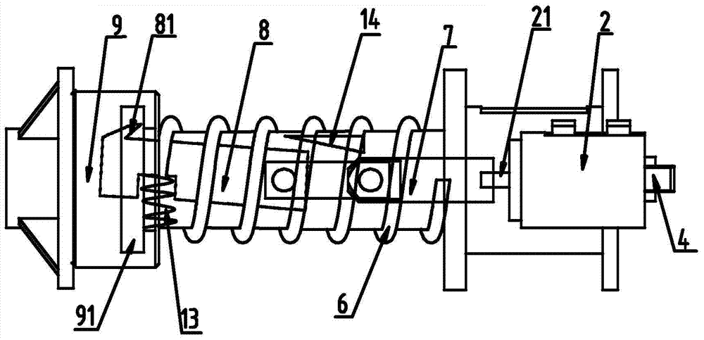
[0037] Such as figure 2 , image 3 As shown, one end of the leading action member 2 is provided with a conduit 5, and the other end is provided with a pin fixing member 4, and the pin fixing member 4 is connected with the pin to be removed, and the leading acting member 2 and The auxili...
Embodiment 2
[0041] Such as Figure 1-3 Shown, described a kind of pin removal device in concrete work, comprises the following steps:
[0042] (1) Connect the pin shaft fixing part 4 with the pin shaft to be removed on the equipment, connect the auxiliary action part 3 and the main action part 2 with the driving device, start the driving device, and drive the auxiliary action part 3 to extend, Prompt the auxiliary active part 3 to act on the surface of the equipment, and generate a pulling force F on the pin shaft to be removed 1 , and F 1=P×S, where P is the working pressure of the driving device, and S is the contact area between the auxiliary parts and the surface of the equipment;
[0043] (2) Operate the leading action member 2 and make it in an extended state, drive the grilling hook 8 to move towards the hammer head 9, and under the action of the elastic member 2 13, the grilling hook head 81 will move the groove 91 hooked;
[0044] (3) Operate the leading action member 2 to re...
Embodiment 3
[0049] The same part of this embodiment and embodiment two will not be repeated, the difference is:
[0050] In the underground construction environment, the pin shaft removal device of the present invention is used to remove the pin shaft of the hydraulic support. The service life of the pin shaft to be removed is 5 years, and the driving device is connected to the hydraulic pipeline of the support. No additional driving device is required, and the application value is high.
[0051] The working pressure generated by the hydraulic pipeline of the support is 31.5MPa, and the main action part 2 and the auxiliary action part 3 are both internal liquid-injected jacks with a cylinder diameter of 100mm and a piston stroke of 300mm, then
[0052] f 1 =P×S=31.5×10 6 ×3.14×0.05 2 =247.275KN.
[0053] The diameter d=18mm of the elastic part-6, its rigidity modulus G=7300kN / mm2, its effective number of turns n=9, its maximum compression amount is 250mm, and the length of the slot 11...
PUM
 Abstract
Description
Claims
Application Information