Supercharge Your Innovation With Domain-Expert AI Agents!

Positioning and straightening mechanism

A straightening and vertical technology, applied in metal processing machinery parts, measuring/indicating equipment, metal processing equipment, etc., can solve problems such as complicated operation and affecting work efficiency

Inactive Publication Date: 2016-04-27
QINGDAO SANLI ZHONGDEMEI WATER EQUIP
View PDF0 Cites 0 Cited by
  • Summary
  • Abstract
  • Description
  • Claims
  • Application Information

AI Technical Summary

Problems solved by technology

[0003] At present, visual inspection and dial indicator alignment are generally used for positioning and alignment. These methods have certain effects, but the operation is complicated and affects work efficiency.

Method used


Image

  • Positioning and straightening mechanism

Examples


Embodiment Construction

[0007] The illustrated embodiments will be described in detail below in conjunction with the accompanying drawings.

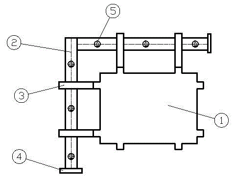
[0008] figure 1 A positioning and straightening mechanism provided by the present invention includes: a special-shaped workpiece (1), a guide rail (2), a slider (3), a stopper (4), and an inner hexagonal screw (5).

[0009] The implementation method is to fix the vertical direction of the guide rail (2) on the left side of the workbench of the machining center with 3 hexagon socket screws (5), and make the other guide rail (2) 90° from the vertical direction and use 3 screws The inner hexagon screw (5) is fixed on the top of the workbench of the machining center, and the length can be determined according to the size of the workbench. Install the sliders (3) on the guide rails one by one, and install two sliders on each guide rail. (Compared to large-scale machining centers, if the guide rails are too long, consider installing 3-4.) Install the stopper (4) at...


PUM


Abstract

The invention provides a positioning and straightening mechanism. The positioning and straightening mechanism comprises a positioning part and a straightening part. The positioning and straightening mechanism disclosed by the invention is remarkable in effect, and has the advantages of preventing unnecessary troubles caused by repeated positioning and straightening during machining of a work piece and greatly improving the work efficiency. The positioning and straightening mechanism is simple to manufacture and low in cost.

Description

technical field [0001] The invention relates to the field of machining center tooling, which is convenient and practical, simple to operate and can greatly improve work efficiency. Background technique [0002] In the process of machining workpieces in machining centers, the machining accuracy of workpieces is too high, the machining shapes are complex, and multiple surfaces are processed. [0003] At present, visual inspection and dial indicator alignment are generally used for positioning and alignment. These methods have certain effects, but the operation is complicated and affects work efficiency. Contents of the invention [0004] The purpose of the present invention is to provide a positioning alignment mechanism which is easy to operate and can greatly improve work efficiency. The invention can quickly locate and straighten special-shaped workpieces and conventional workpieces. [0005] In order to achieve the above-mentioned purpose, the present invention provide...

Claims


Application Information

Patent Timeline
IPC IPC(8): B23Q17/20
Inventor 张明亮王学成许良芝
Owner QINGDAO SANLI ZHONGDEMEI WATER EQUIP
Features
  • R&D
  • Intellectual Property
  • Life Sciences
  • Materials
  • Tech Scout
  • Unparalleled Data Quality
  • Higher Quality Content
  • 60% Fewer Hallucinations
Learn More