Method for producing a part and device for carrying out this method

a technology of generative manufacturing and parts, applied in the direction of auxillary shaping apparatus, electron beam welding apparatus, wood working apparatus, etc., can solve the problems of poor surface quality, insufficient accuracy, and demand for mechanical finishing operation, and achieve the effect of reducing tool wear, facilitating machining, and reducing the wear of tools

Inactive Publication Date: 2006-02-28
HERMLE MASCHENBAU
View PDF13 Cites 114 Cited by
  • Summary
  • Abstract
  • Description
  • Claims
  • Application Information

AI Technical Summary

Benefits of technology

[0077]To form contours, millers or grinding tools are preferably used. Whether form millers are used, or inclinations are e.g. achieved by inclining the tool, these measures come up to the same. The predominant processing of a support material that can be machined more easily, instead of a high-quality construction material, effects faster machinability, lower tool wear and offers the ...

Problems solved by technology

Since in the direct manufacture of metallic parts the necessary progress has not been achieved up to now, metallic parts, particularly those with complicated geometries, are even nowadays mostly produced in indirect methods, such as precision casting or sand casting, which have already been known for a long time.
Nowadays, however, this is often ruled out by problems arising in generative manufacturing methods, e.g. objectionable step effect, porous parts, small constructional space, poor surface quality, inadequate accuracy, demand for a mechanical finishing operation, stresses and distortion, restricted use of series material, only limited production of undercuts, no local use of different construction materials, inadequate properties of the materials, only limited production of functional parts.
A problem arising in the thermal spraying at high temperatures is the oxide formation of the construction material.
Since the use of inert gas (e.g. argon) as an atomizer gas is mostly not economic in the amounts needed, a certain oxide content in the construction material must be accepted.
In the conventional selective laser sintering in a powder bed, the problem arises that neighboring particles are molten or partly molten in an unintended way.
This is detrimental to the surfa...

Method used


Image

  • Method for producing a part and device for carrying out this method
  • Method for producing a part and device for carrying out this method
  • Method for producing a part and device for carrying out this method

Examples


Embodiment Construction

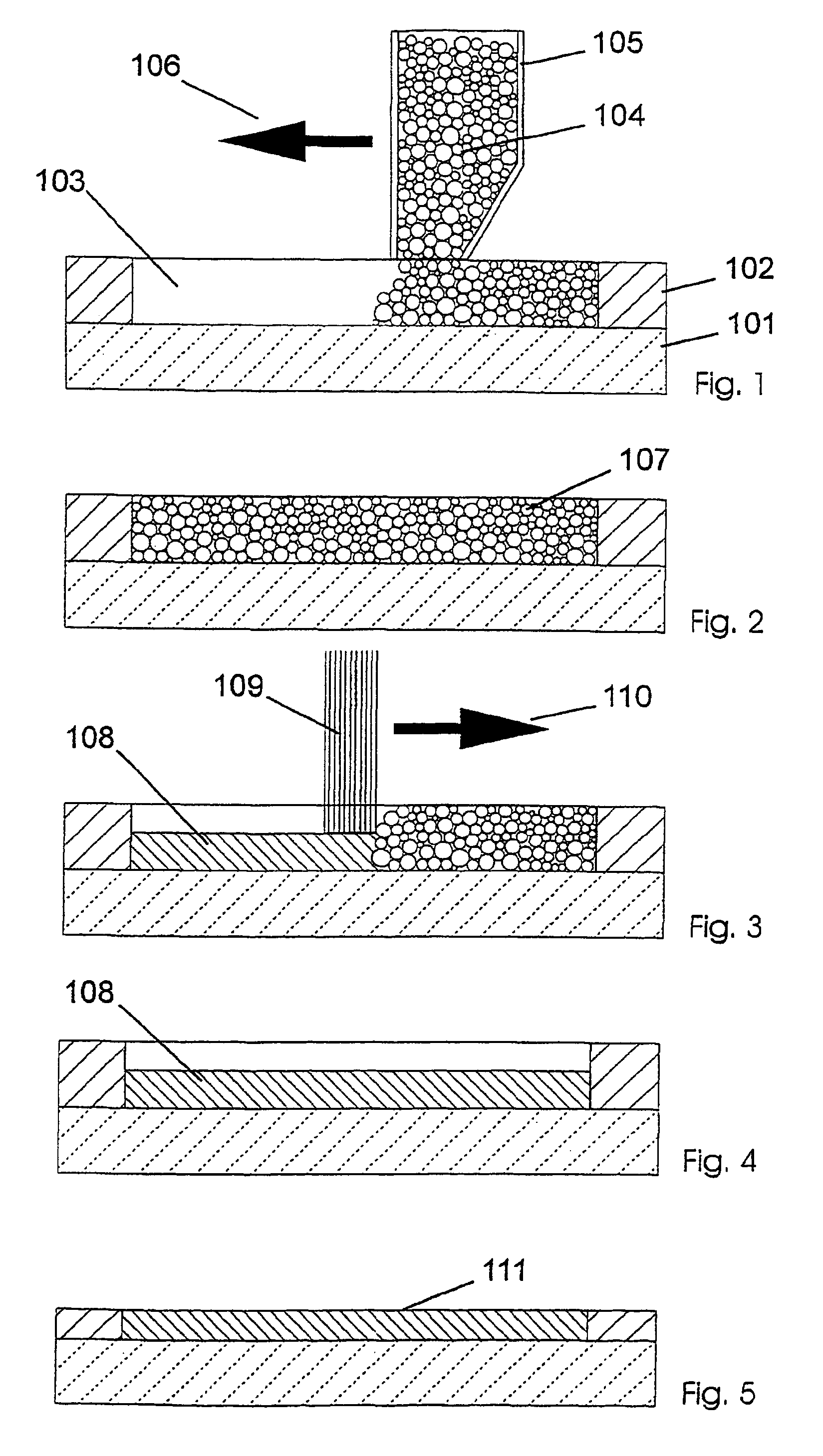
[0115]FIGS. 1 to 5 depict the production of a part 108 according to a first preferred embodiment. A support material 102 is applied to a substrate 101 or a preceding layer. The support material 102 can be applied according to the contour of the desired part 108 in a defined way or in a flat form with subsequent production of the recesses 103 needed. The recess 103 may be larger than the contour of the desired part 108 if a finishing operation for the layer on the construction material 107 is to be carried out. In a further step, the recess 103 is filled with a construction material 107. To this end a supply container 105, which contains the construction material 104, is guided in the direction of arrow 106 over the recess 103 existing in the support material 102. In a further step, the construction material 107 is molten in itself and optionally molten (connected by melt metallurgy) with the layer positioned thereunder with a laser 109, which moves e.g. in the direction of arrow 110...


PUM

PropertyMeasurementUnit
Timeaaaaaaaaaa
Timeaaaaaaaaaa
Timeaaaaaaaaaa

Abstract

The present invention relates to a method for producing a part (108, 200, 300), comprising the following steps:
    • a) applying a first flat layer consisting of a support material (102, 202, 302), to a construction platform (101, 201, 301),
    • b) introducing at least one recess (103, 203, 303) into the support material (102, 202, 302),
    • c) filling the recess (103, 203, 303) with a construction material (104, 204, 304),
    • d) applying a further layer of support material (102, 202, 302),
    • e) repeating steps b) through d) until completion of the part (108, 200, 300), and
    • f) removing the support material (102, 202, 302).
This method is to provide a manufacturing method and a device that combine the advantages of the layerwise construction (rapid prototyping) with the advantages of machining (e.g. high-speed cutting) and particularly permit the production of sharp-edged contours.
Furthermore, the present invention relates to a device for carrying out the method.

Description

BACKGROUND AND SUMMARY OF THE INVENTION[0001]The present invention relates to a method for producing a part and to a device for carrying out said method. Particularly, the invention relates to a generative manufacturing method for producing metallic or composite parts.[0002]In the past years many different generative methods for the direct or indirect production of mostly non-metallic parts were developed and partly commercialized.[0003]Since in the direct manufacture of metallic parts the necessary progress has not been achieved up to now, metallic parts, particularly those with complicated geometries, are even nowadays mostly produced in indirect methods, such as precision casting or sand casting, which have already been known for a long time.[0004]The most wide-spread method for the direct manufacture of metallic parts is milling or cutting. With the considerable speed increases provided by high-speed cutting (HSC), the attempt has already been made to combine said technology wit...

Claims


Application Information

Patent Timeline
IPC IPC(8): B29C67/00B22F3/105B22F3/00
CPCB22F3/008B29C67/0092Y10T29/4998Y10T29/49885Y10T29/49886Y10T29/49982B29C64/40B33Y10/00B33Y30/00Y02P10/25B22F10/62B22F10/28B22F10/66B22F10/43B22F12/90B22F10/50B22F10/64B29C67/00
Inventor DIRSCHERL, MARKUS
Owner HERMLE MASCHENBAU
Why Eureka
Try Eureka