Method of Machining Workpiece with Machine Tool

a technology of machining and workpiece, applied in the direction of instruments, electric controllers, program control, etc., can solve the problems of short life, damage to the machine tool, wear and defects, etc., and achieve the effect of stabilizing machining quality, improving machining efficiency, and reducing wear and damag

Active Publication Date: 2013-12-05
DMG MORI SEIKI CO LTD +1
View PDF7 Cites 3 Cited by
  • Summary
  • Abstract
  • Description
  • Claims
  • Application Information

AI Technical Summary

Benefits of technology

[0026]As described in detail above, according to the present disclosure, tool wear caused by fluctuations in cutting resistance inevitably occurring under intermittent cutting can be reduced, thereby stabilizing machining quality and improving machining efficiency.

Problems solved by technology

In general, machine tool damage (such as wear and defects) are thought to depend on the material and shape of the tool, the magnitude of cutting resistance to be acted on the tool in cutting, and other factors.
When the tool is damaged quickly, that is the tool life is short, machining quality is disadvantageously unstabilized.
Moreover, the tool is required to be exchanged often, thereby disadvantageously degrading machining efficiency.

Method used


Image

  • Method of Machining Workpiece with Machine Tool
  • Method of Machining Workpiece with Machine Tool
  • Method of Machining Workpiece with Machine Tool

Examples


Embodiment Construction

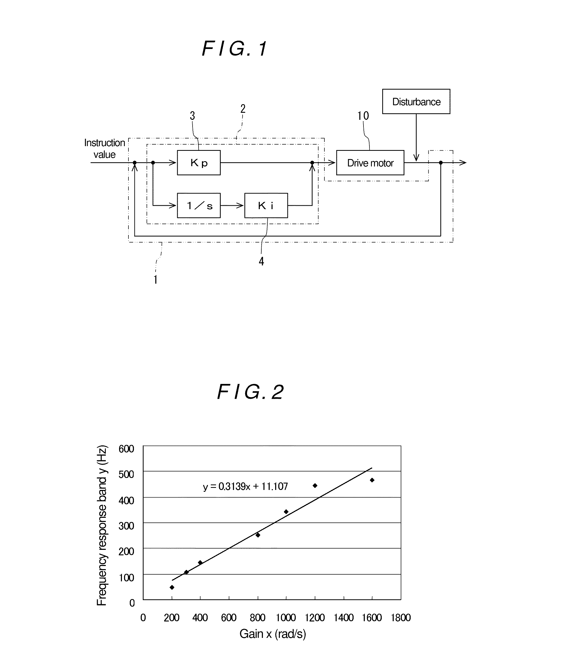
[0056]Specific embodiments of the present disclosure are described below. FIG. 1 is a block diagram of a general feedback control model in a rotation drive motor configuring a spindle device or a feed drive motor configuring a feed device in a machine tool.

[0057]In FIG. 1, a reference numeral 10 denotes a drive motor corresponding to the rotation drive motor or the feed drive motor. A feedback control unit (a control system) 1 includes a PI control unit 2, generating a control signal corresponding to an instruction value and controlling the drive motor 10 with the generated control signal.

[0058]In the PI control unit 2, by adjusting a proportional gain 3 and an integral gain 4 (which are hereinafter simply referred to as “gain”), the frequency response band of the feedback control unit 1 can be adjusted. A relation between gain and frequency response band is depicted in FIG. 2. FIG. 2 depicts a relation between gain and frequency response band of a permanent magnet synchronous motor...


PUM

PropertyMeasurementUnit
frequencyaaaaaaaaaa
frequencyaaaaaaaaaa
frequencyaaaaaaaaaa

Abstract

A workpiece is machined by setting a frequency response band of a control system for a rotation drive motor or a feed drive motor so that tool abrasion is within a predetermined allowable range. The frequency response band may be adjusted by adjusting a proportional gain and an integral gain. With the workpiece machined by such a process, where the frequency response band maintains tool abrasion within the allowable range, machining quality and efficiency are improved.

Description

TECHNICAL FIELD[0001]The present disclosure relates to methods of machining a workpiece with a machine tool and, more specifically, to machining methods capable of reducing tool wear even in intermittent cutting.[0002]Background of the Disclosure[0003]In general, machine tool damage (such as wear and defects) are thought to depend on the material and shape of the tool, the magnitude of cutting resistance to be acted on the tool in cutting, and other factors. When the tool is damaged quickly, that is the tool life is short, machining quality is disadvantageously unstabilized. Moreover, the tool is required to be exchanged often, thereby disadvantageously degrading machining efficiency.[0004]Thus, conventionally, cutting tools with high wear resistance have been diligently and continuously developed, in view of structural stiffness in addition to their material and shape. Also, machine tools have been improved everyday to stabilize a machining environment, such as stiffness, based on ...

Claims


Application Information

Patent Timeline
Patent Type & Authority Applications(United States)
IPC IPC(8): B23Q5/54
CPCB23Q5/54G05B11/42G05B19/4163G05B2219/43132Y10T409/303808
Inventor SOSHI, MASAKAZUISHII, SHINJIYAMAZAKI, KAZUO
Owner DMG MORI SEIKI CO LTD
Why Eureka
Try Eureka