Hole machining drill bit and hole machining method suitable for carbon fiber composite materials

A hole processing method and composite material technology, applied in drilling/drilling equipment, cutting tools for lathes, metal processing equipment, etc., can solve problems such as unstable hole quality, short tool life, and low product qualification rate , to achieve the effect of improving connection and assembly quality, improving product qualification rate, and improving the quality of the whole machine

Active Publication Date: 2016-02-24
HUNAN UNIV OF SCI & TECH
View PDF9 Cites 3 Cited by
  • Summary
  • Abstract
  • Description
  • Claims
  • Application Information

AI Technical Summary

Problems solved by technology

However, in the existing technology, 60% to 80% of the structural damage of aerospace vehicles occurs at the connection parts, which also puts forward high requirements on the connection and assembly quality of resin-based carbon fiber composite parts
At present, there are many problems in the hole-making process of composite materials. Traditionally, high-speed steel or carbide tools with ordinary twist drills are used for drilling. There are burrs at the outlet and delamination or even tearing at the exit. Not only is the production efficiency low, but there are also systems such as unstable hole quality, short tool life, splitting and shrinkage holes in hole making, and low product qualification rate. question

Method used


Image

  • Hole machining drill bit and hole machining method suitable for carbon fiber composite materials
  • Hole machining drill bit and hole machining method suitable for carbon fiber composite materials
  • Hole machining drill bit and hole machining method suitable for carbon fiber composite materials

Examples


Embodiment Construction

[0015] The specific embodiments of the present invention will be further described below in conjunction with the accompanying drawings. It should be noted here that the descriptions of these embodiments are used to help understand the present invention, but are not intended to limit the present invention. In addition, the technical features involved in the various embodiments of the present invention described below may be combined with each other as long as they do not constitute a conflict with each other.

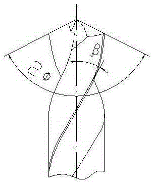
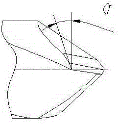
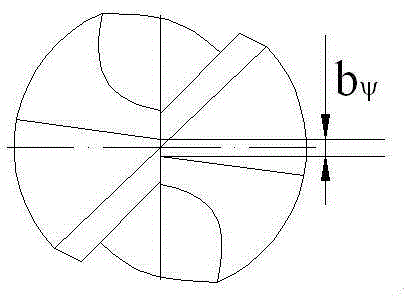
[0016] as attached figure 1 , attached figure 2 And attached image 3 As shown, the drill bit suitable for hole processing of carbon fiber composite materials has a diameter of 4 mm to 6 mm, a drill point angle 2Φ of 92.5° to 97.5°, a helix angle β of 25° to 30°, and a relief angle α of 20° to 25°. °, length of chisel edge b ψ It is 0.02 to 0.03 times the diameter of the drill bit. The present invention preferably selects the diameter of the drill bit as 6mm, the d...


PUM

PropertyMeasurementUnit
diameteraaaaaaaaaa
angleaaaaaaaaaa
diameteraaaaaaaaaa

Abstract

The invention discloses a hole machining drill bit and a hole machining method suitable for carbon fiber composite materials. The diameter of the drill bit is 6 mm, the drill point angle of the drill bit is 96 degrees, the helix angle of the drill bit is 28 degrees, the relief angle of the drill bit is 25 degrees, the length of a chisel edge is 0.028 time of the diameter of the drill bit, and the roughness of the surface of a front tool face and the surface of a rear tool face of the drill bit is 0.65 micrometer. The specific using method comprises the steps that the rotation speed of the drill bit is set to be 2350 r/min, and the feeding speed is set to be 0.018 mm/r. By means of the hole machining drill bit and the hole machining method, the phenomena that burrs occur at an inlet, and layering even fracture occurs at an outlet in the machining process of the carbon fiber composite materials are effectively avoided, the machining precision of the carbon fiber composite materials is effectively improved, and the product qualification ratio of the machining of the carbon fiber composite materials is increased; the connection and assembling quality of aerospace and national defense equipment is improved, and the quality of the whole equipment is effectively improved.

Description

technical field [0001] The invention relates to the field of carbon fiber composite material processing, in particular to a hole processing drill suitable for carbon fiber composite materials and a hole processing method. Background technique [0002] With the development of aerospace technology and the upgrading of national defense equipment, lightweight and high power density equipment has attracted great attention from all over the world. Carbon fiber composite materials have light weight, high strength, high modulus, wear resistance, high temperature resistance, and Corrosion, anti-fatigue and other series of superior properties are actively applied and pursued by various countries. However, in the prior art, 60% to 80% of the structural damage of aerospace vehicles occurs at the connection parts, which also puts forward high requirements on the connection and assembly quality of resin-based carbon fiber composite parts. At present, there are many problems in the hole-m...

Claims


Application Information

Patent Timeline
Patent Type & Authority Applications(China)
IPC IPC(8): B23B51/00B23B35/00
CPCB23B35/00B23B51/00B23B2226/27B23B2251/04B23B2251/043
Inventor 李鹏南邱新义唐思文陈浩唐小同唐玲艳
Owner HUNAN UNIV OF SCI & TECH
Why Eureka
Try Eureka