Method for near-net-shape machining of curved contours

a machining method and contour technology, applied in the direction of grinding machines, program control, instruments, etc., can solve the problems of increasing the deformation effect of grinding force, local reduction of strength, and substantial deviation between the desired setpoint contour and the actual contour, so as to reduce the number of semi-finished products, increase the machining quality, and reduce the rejection of curved workpieces in particular

Inactive Publication Date: 2009-08-27
MTU AERO ENGINES GMBH
View PDF10 Cites 3 Cited by
  • Summary
  • Abstract
  • Description
  • Claims
  • Application Information

AI Technical Summary

Benefits of technology

[0010]The object of the present invention is therefore to provide a method for near-net-shape machining of curved contours with the aid of 2D or 3D curve grinding operations. By using this method, the number of tests required to set up a grinding machining operation and therefore the number of semifinished products required for it are to be minimized. At the same time, rejects in fabrication of curved workpieces in particular are to be reduced by increasing the machining quality. Use of complex chucking devices should be avoided and the cutting performance should be maximized.

Problems solved by technology

One problem in manufacturing curved contours in particular is that there is often a substantial deviation between the desired setpoint contour and the actual contour achieved.
In the extreme case, temperatures in the range of the melting point of the particular material may occur during grinding, thereby resulting in substantial thermal expansion as well as a local reduction in strength, which further increases the deforming effect of the grinding forces.
However, the possibilities for intervention that may be achieved here are extremely limited, accordingly resulting in unsatisfactory results.
Furthermore, an attempt may be made to reduce deformation of the workpiece during machining by blocking using a plurality of fixation points and a corresponding chucking device having a complex design.
However, in this case increased mechanical stresses occur in the material, which is unable to expand freely despite the elevated temperature, so that this procedure may in turn result in problems such as damage to the material.
However, one unwanted side effect here in particular is a correspondingly longer machining time.
For these tests, a corresponding semifinished product is needed each time, and the analysis of each test is time-intensive because the complex contours must be measured each time and the paths to be traveled must be readjusted.
This results in high costs in setting up a procedure accordingly as well as a long setup time.
In the case of inadequate preliminary tests, as well as due to technical limitations, this results in an increased number of rejects.
These disadvantages are serious in particular with complex components, where semifinished products are already being manufactured in cost-intensive procedures and / or when using expensive materials.

Method used


Image

  • Method for near-net-shape machining of curved contours
  • Method for near-net-shape machining of curved contours
  • Method for near-net-shape machining of curved contours

Examples


Embodiment Construction

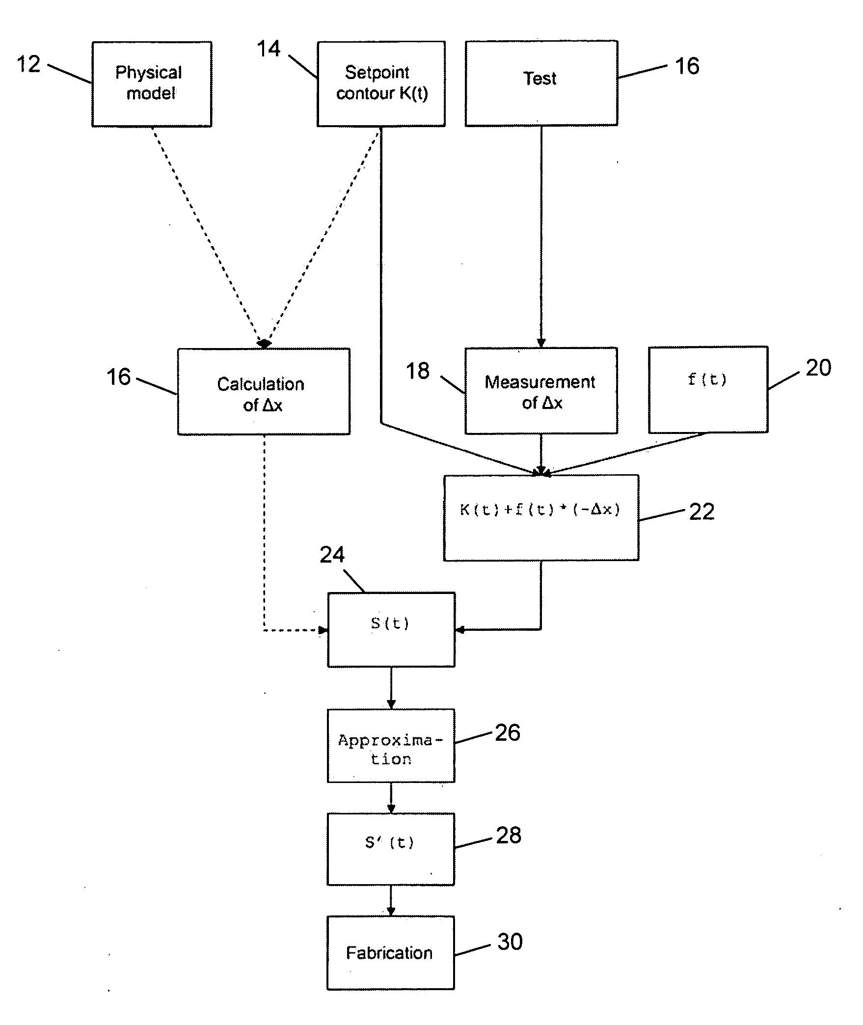
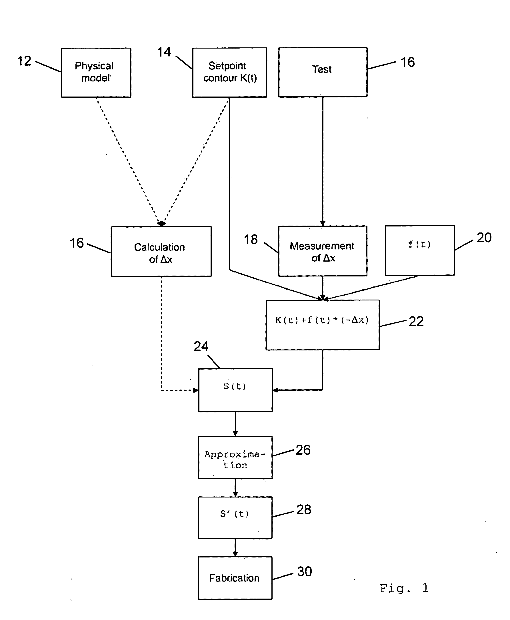
[0030]FIG. 1 shows a flow chart of the two variants of the method according to the present invention.

[0031]In the left half of the figure, the “analytical” or “numerical” variant of the method according to the present invention is shown. Components of the diagram corresponding to this variant are indicated by dashed connecting lines.

[0032]Thus, in a step 12 a setpoint contour K(t) which corresponds to the desired workpiece shape after machining is predefined. Furthermore, in a step 10, the physical behavior of the workpiece during machining is stored in the form of a suitable model.

[0033]With the help of analytical or numerical methods, in a step 16, a calculation of an expected measured deviation Δx will now be performed.

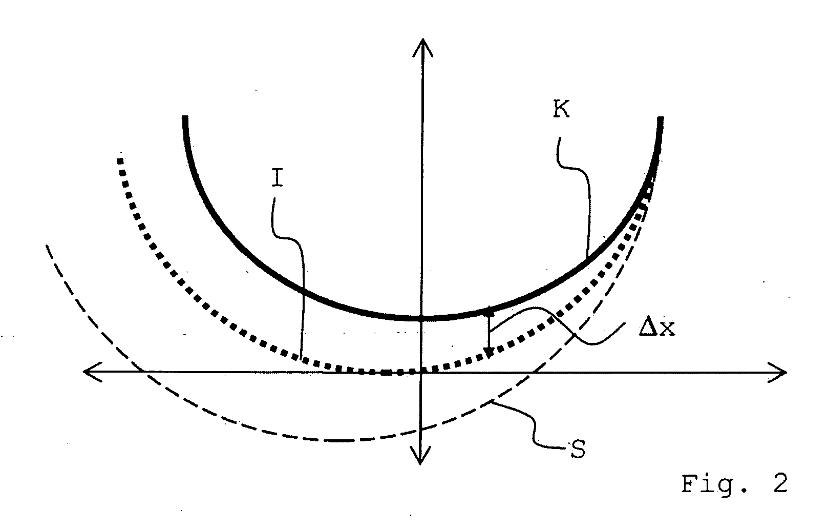
[0034]The difference between deviation Δx and setpoint correction K(t) corresponds essentially to path movement S(t) actually to be programmed. The path movement S(t) to be programmed is determined in a step 24 based the difference between deviation Δx and setpoint...


PUM

PropertyMeasurementUnit
forceaaaaaaaaaa
temperatureaaaaaaaaaa
pressureaaaaaaaaaa

Abstract

A method relating to near-net-shape machining of curved contours such as those occurring, for example, in the fabrication of blades for propulsion engines and the like is described. Accordingly, the shape error in curve grinding is minimized by suitable compensation functions, in particular by interpolating and approximating cubic splines. The present method minimizes the number of tests required to set up a grinding machining operation and thus the number of semifinished products required to do so. At the same time, rejects in fabrication of curved workpieces are reduced by increasing the machining quality. The use of complex chucking devices is avoided and cutting performance is maximized.

Description

[0001]Priority is claimed to German Patent Application DE 10 2008 010 982.7, filed Feb. 25, 2008, the entire disclosure of which is hereby incorporated by reference herein.[0002]The present invention relates to the field of machining of workpieces, in particular by CNC machine tools, and here specifically by grinding machines. More specifically, it relates to a method for near-net-shape machining of curved contours, such as those which occur, for example, in the fabrication of blades for propulsion engines and the like.BACKGROUND OF THE INVENTION[0003]Grinding, among other methods, is used for manufacturing precisely shaped surfaces. In contrast with methods using a geometrically specific cutting edge, grinding methods are classified as machining methods having a geometrically indeterminate cutting edge. Sharp-edged grains of a certain order of magnitude embedded in a binder are often used as the separating agent. By repeated movement of the grinding tool along the surface to be mac...

Claims


Application Information

Patent Timeline
Patent Type & Authority Applications(United States)
IPC IPC(8): B24B49/04G05B19/404G05B19/4099
CPCB24B19/14B24B51/00B24B49/16B24B49/14
Inventor GEISEL, MARK
Owner MTU AERO ENGINES GMBH
Why Eureka
Try Eureka