Knitting needle and bar for said needle

a technology of knitting needles and sinkers, which is applied in the direction of knitting, weft knitting, textiles and papermaking, etc., can solve the problems of considerable cost and complexity of manufacturing, and achieve the effect of minimal manufacturing cost and effort and high positioning accuracy

Active Publication Date: 2007-07-26
GROZ BECKERT KG
View PDF5 Cites 2 Cited by
  • Summary
  • Abstract
  • Description
  • Claims
  • Application Information

AI Technical Summary

Benefits of technology

[0006]In order to connect the inventive knitting tool to the bar, said tool has a shaft with at least one narrow side where two projections are arranged at a distance from each other. These projections extend away from the shaft and have an abutment surface on their face away from the shaft. This abutment surface is used to position the knitting tool on the bar. Considering the bar, the remaining narrow side is configured in such a manner that it does not abut against the bar. If the knitting tool is arranged in a groove, the narrow side does not abut against the groove bottom, but maintains a distance of, for example, a few tenths of a millimeter, therefrom. In so doing, the distance is dimensioned such that the manufacturing tolerances are of no consequence for positioning the knitting tool from the viewpoint of the straightness or the dimensional stability of the narrow side or from the viewpoint of the straightness or the dimensional stability of the groove bottom. Consequently, considering the knitting tool, the manufacturing costs and efforts can be substantially reduced. For example, different process operations for fine-machining and / or for calibrating the knitting tool with respect to the projections can be restricted—strictly speaking—to the faces of said projections. Thus, a gain in manufacturing safety and a reduction of the manufacturing costs and effort is achieved with the inventive knitting tools, even considering only conventional needle bars that have a straight and continuous groove bottom.
[0008]The plurality of parallel grooves that act to accommodate the knitting tools are now traversed by two wider grooves that are parallel to each other and extend along the longitudinal direction of the needle bar. These latter grooves are preferably at right angles relative to the remaining narrower grooves. These two transversely extending grooves have a width of 3 mm, for example. In so doing, they are slightly deeper than the first-mentioned narrow grooves that accommodate the knitting tools. They can be milled continuously in one run, whereby their groove bottom forms the abutment surface or reference surface for the projections of the knitting tools. Due to the expected reduced tool wear of the wider groove miller, the shorter path traveled by said miller along the needle bar, and due to the circumstance that the two transverse grooves can be milled in one run, high machining accuracy can be achieved in a simple manner. The reliable depth tolerance of the grooves used to accommodate the knitting tools can thus be selected to be even greater, without developing any disadvantages from the viewpoint of the positioning accuracy of the knitting tools.
[0011]Preferably, the knitting tool is designed as a knitting needle or as a hooked needle in that it is provided with a hook on one end. Considering the high positioning accuracy that is to be achieved with minimal manufacturing costs and efforts, this hooked needle is recommended for the cooperation with sliders. To this extent, the hooked needles may also be referred to as compound needles, even though the sliders are supported by another bar. The knitting tool, however, may also be another tool.

Problems solved by technology

This makes extreme demands on the manufacture of the knitting needles, as well on the manufacture of the bar, which means that manufacturing is considerably expensive and complex.

Method used


Image

  • Knitting needle and bar for said needle
  • Knitting needle and bar for said needle
  • Knitting needle and bar for said needle

Examples


Embodiment Construction

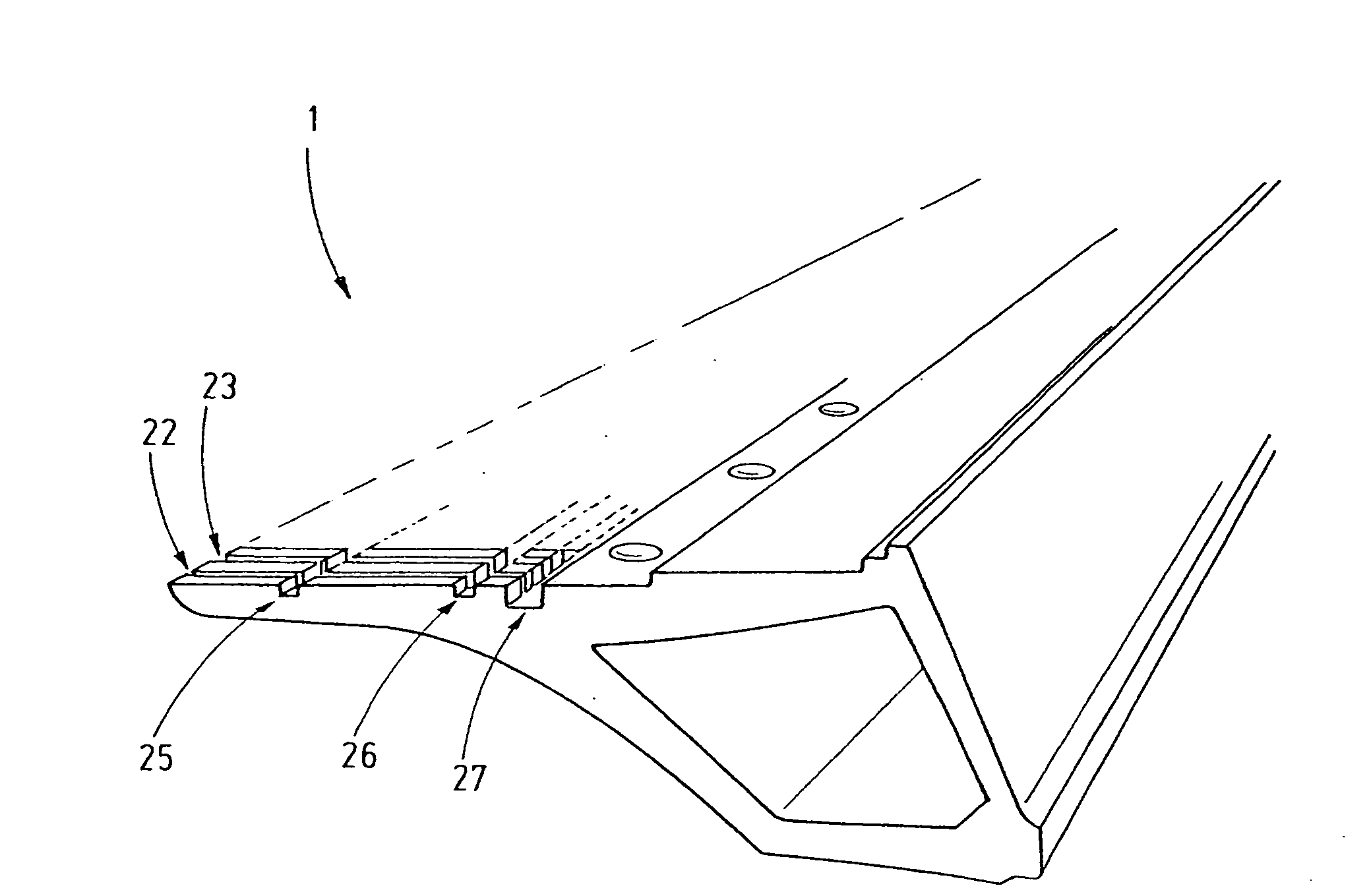
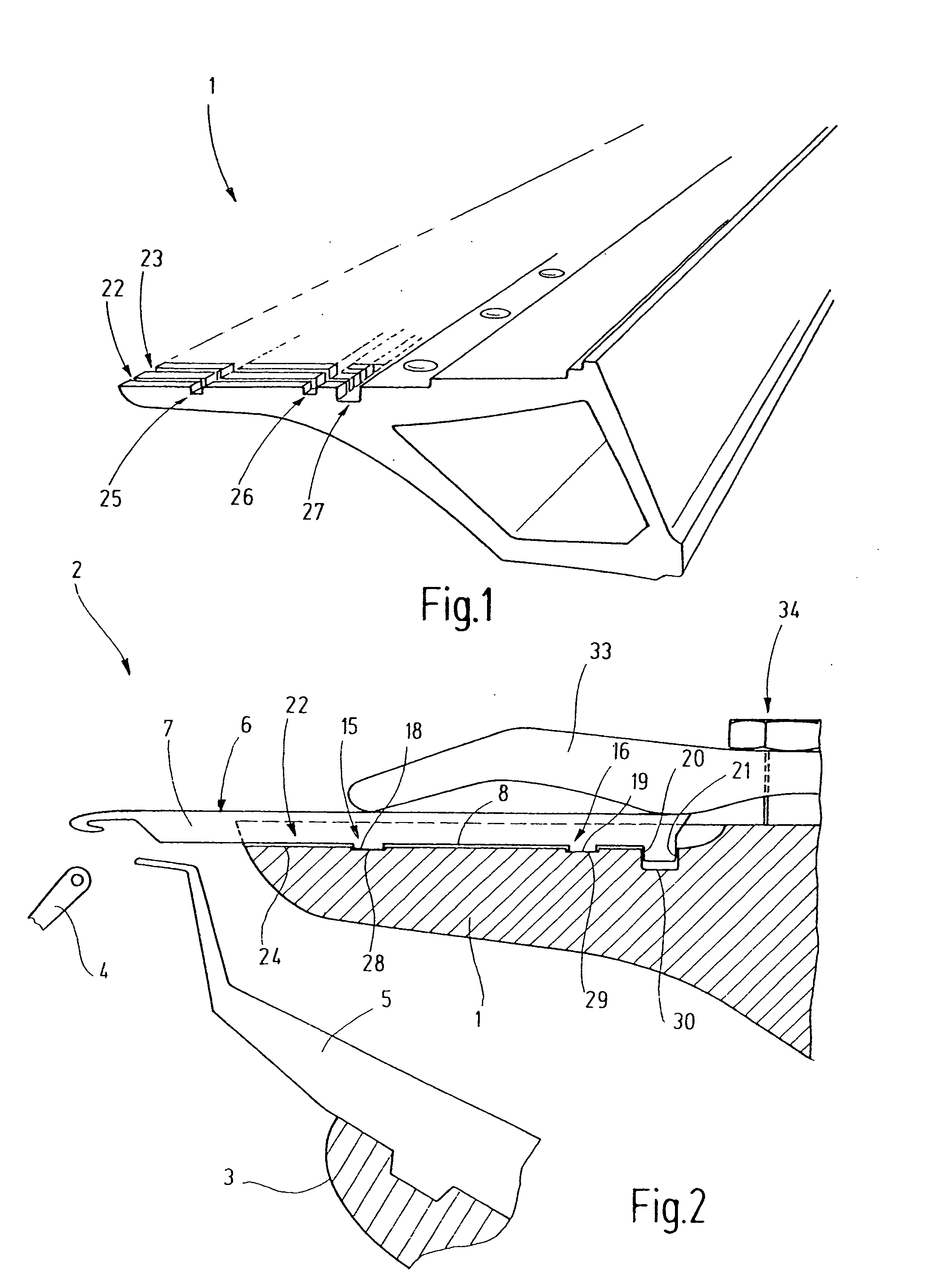
[0023]FIG. 1 shows a needle bar 1 which belongs to the knitting system 2 of a warp knitting machine. The knitting system 2 comprises several holding devices configured as bars, which include the needle bar 1, a slider bar 3 and, preferably, several apertured needle bars that hold apertured needles 4 and are not shown here. The slider bar 3 is provided with sliders 5, and the needle bar 1 is provided with knitting needles 6. Together, the knitting needles 6, the sliders 5 and the apertured needles 4 form knitting tools that are held in large numbers at uniform distances parallel to each other. In so doing, each knitting needle 6 is associated with exactly one slider 5 which must precisely interact with the knitting needle 6, which is why the knitting needle 6 and the slider 5 must be positioned precisely relative to each other.

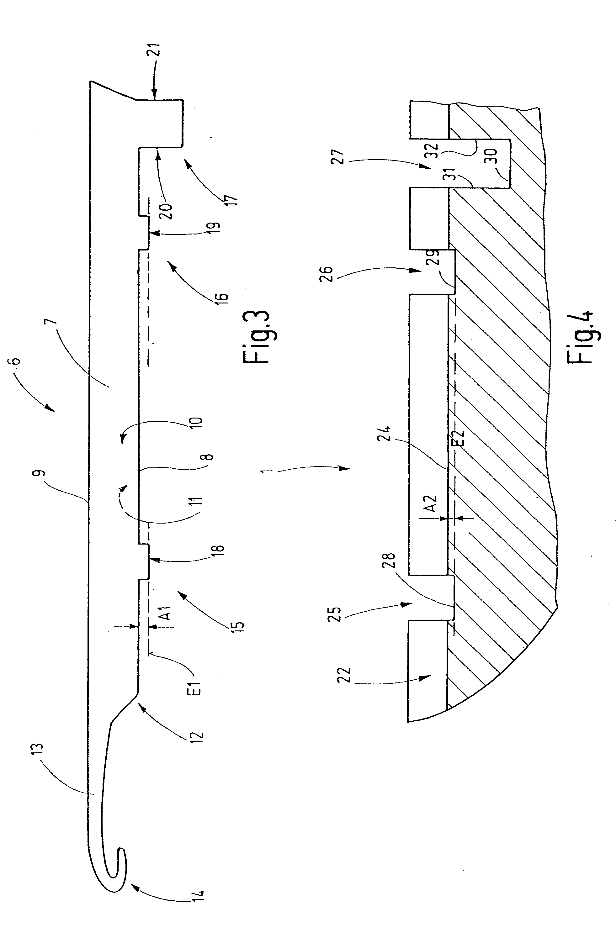
[0024]FIG. 3 is a separate illustration of the knitting needle 6. This needle has a body 7 which is configured as a thin sheet metal part. To do so, the body 7...


PUM


Abstract

The inventive knitting tools, in particular knitting needles (6), have a body (7) which, for alignment, has on its narrow side projections (15, 16) which have precisely machined abutment surfaces (18, 19) on their end faces. The abutment surfaces (18, 19), can be produced, for example, during a suitable stage of the manufacturing process. One of the projections (15, 16) or an additional projection (17) can be provided with abutment surfaces (20, 21) which are used for longitudinal positioning of the knitting tool. Corresponding grooves (25, 26, 27) in the needle bar (1) are assigned to the projections (15, 16, 17).

Description

CROSS REFERENCE TO RELATED APPLICATION[0001]This application claims the priority of European Patent Application No. 06 001 512.0, filed on Jan. 25, 2006, the subject matter of which, in its entirety, is incorporated herein by reference.BACKGROUND OF THE INVENTION[0002]The invention relates to a knitting needle and to a sinker bar to receive such a needle.[0003]Warp knitting machines comprise several bars which support knitting tools or loop-forming tools such as apertured needles, hooked needles configured as compound needles, or sliders. In so doing, each of the bars forms a long support extending transversely to the direction of movement of the flat, knitted textile product, whereby these supports hold the appropriate knitting tools or loop-forming tools and can be moved consistent with the knitting or loop-forming process. As a result of this, all the knitting tools of a bar are moved fully synchronized with respect to each other. In so doing, the knitting tools of the different ...

Claims


Application Information

Patent Timeline
Patent Type & Authority Applications(United States)
IPC IPC(8): D04B35/04
CPCD04B35/02D04B27/06D04B15/24D04B15/00D04B15/06
Inventor JURGENS, ERICBUTZ, TORSTENKIRCHMAIR, KLAUSFEHRENBACHER, ECKHARD
Owner GROZ BECKERT KG
Why Eureka
Try Eureka