Integrated deburring finish machining turning method and cutter

A finishing turning and deburring technology, which is applied in the direction of lathe tools, turning equipment, manufacturing tools, etc., can solve the problem of surface roughness value reduction, reduce surface roughness and tool wear, improve processing efficiency, Easy to adjust the effect

Inactive Publication Date: 2013-03-27
NANJING AGRICULTURAL UNIVERSITY
View PDF5 Cites 4 Cited by
  • Summary
  • Abstract
  • Description
  • Claims
  • Application Information

AI Technical Summary

Problems solved by technology

In addition, after adopting the deburring integrated finishing test bench, it is found under the three-dimensional microscope that the jagged tops of the machined surface protrusions are obviously scraped off, and the surface roughness value is significantly reduced

Method used


Image

  • Integrated deburring finish machining turning method and cutter
  • Integrated deburring finish machining turning method and cutter
  • Integrated deburring finish machining turning method and cutter

Examples


Embodiment Construction

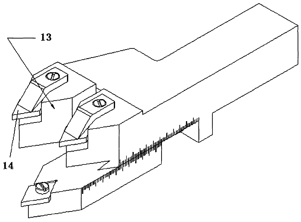
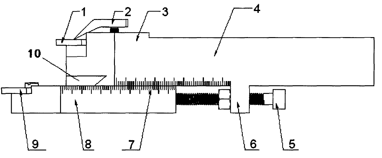
[0020] Such as figure 1 with figure 2 Shown, cutter of the present invention is by 1, cutting blade; 2, pressure head; 3, cutting head; 4, knife handle; 5, precision screw rod; 9. Deburring blade; 10. Dovetail guide rail; 13. Finishing cutter head; 14. Finishing blade composition.

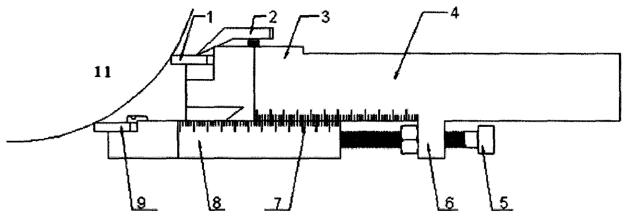
[0021] Such as image 3 As shown, the cutting blade 1 is at the upper part, which is centered with the center of the workpiece; the deburring blade 9 is at the lower part, and the vertical distance between the two base surfaces is L. When the radius of the workpiece is R1, the elongation of the deburring blade 9 is:

[0022] AE = R 1 - R 1 2 - L 2

[0023] At this time, the cutting edge of the cutting blade 1 and the cutting edge of the deburring blade 9 are just on the arc with the workpiece axi...


PUM


Abstract

The invention relates to an integrated deburring finish machining turning method and a cutter and belongs to the field of mechanical machining. The integrated deburring finish machining turning method is characterized in that only one cutter is used, and deburring cutting and finish machining are conducted automatically during rough machining of turning. The cutter is provided with three cutting heads and can install three blades. A cutter point of a cutting blade (1) and a cutter point of a deburring blade (9) are both on an arc with a workpiece axis as a circular center and turning radius as the radius. Simultaneously, a main cutting edge of the cutting blade and a main cutting edge of the deburring blade are coincided with a bus of a surface to be machined. A cutting head (3) is parallel to a finish machining cutting head (13), and after the blades are installed, a connecting line of two blade cutter points is parallel to the workpiece axis. When the cutting blade (1) cuts a workpiece, burrs of the surface to be machined are exactly scraped off by the deburring blade (9), and protrusions of a machined surface are just scraped off by a finish machining blade (14).

Description

Technical field [0001] The invention relates to a method and a cutting tool capable of realizing integrated deburring and finishing during rough machining when used for outer circle turning, and belongs to the field of mechanical processing. Background technique [0002] During the cutting process of metal, chips will flow along the cutting edge and separate from the workpiece. The protrusion remaining on the processed surface of the workpiece is called surface roughness, and the protrusion remaining on the surface to be processed is called cutting burr. Surface roughness and cutting burrs usually remain on the machined surface in the form of jagged edges. [0003] The larger the surface roughness value, the higher the protrusion on the processed surface of the workpiece, the smaller the effective contact area between the mating surfaces of the parts, the greater the pressure, and the faster the wear; at the same time, the surface roughness will affect the tight fit of the t...

Claims


Application Information

Patent Timeline
Patent Type & Authority Applications(China)
IPC IPC(8): B23B1/00B23B27/00
Inventor 肖茂华杨飞朱思洪傅秀清朱跃
Owner NANJING AGRICULTURAL UNIVERSITY
Why Eureka
Try Eureka