
Shift device

A technology of shifting device and block body, which is applied in the direction of control device, transmission device control, transportation and packaging, etc., which can solve the problem of shift lever movement restriction and achieve the effect of easy displacement

Active Publication Date: 2016-04-27
KK TOKAI RIKA DENKI SEISAKUSHO
View PDF9 Cites 7 Cited by
  • Summary
  • Abstract
  • Description
  • Claims
  • Application Information

AI Technical Summary

Problems solved by technology

[0002] In the shift lever device described in Patent Document 1 below, the movement of the shift lever is restricted by engaging the positioning pin of the rod in the shift lever with the engaging portion of the positioning plate.

Method used


Image

  • Shift device
  • Shift device
  • Shift device

Examples


Embodiment Construction

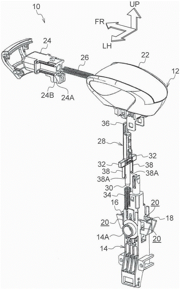
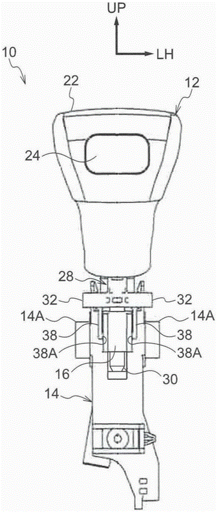
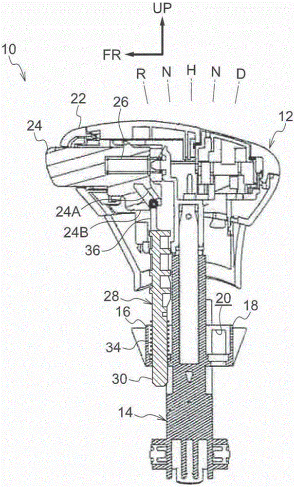
[0024] exist figure 1 FIG. 2 shows an exploded perspective view of a shift lever device 10 serving as a shift device according to an embodiment of the present invention as viewed obliquely from the left rear. and, in figure 2 A front view of the shift lever assembly 10 from the front is shown in image 3 A side view of the shift lever device 10 from the left is shown in . In addition, in the drawings, the arrow FR indicates the front of the shift lever device 10 , the arrow LH indicates the left side of the shift lever device 10 , and the arrow UP indicates the upper side of the shift lever device 10 .

[0025] The shift lever device 10 of the present embodiment is a so-called straight and linear shift lever device. The shift lever device 10 is a floor-mounted shift lever device, and is installed on a floor portion of a vehicle interior of a driver's seat (not shown) of a vehicle (automobile) in the vehicle width direction, at the front and left of the shift lever device 1...


PUM


Abstract

In a shift lever device 10, a detent rod 28 is assembled to a lever main body 14, and when a detent pin 32 of the detent rod 28 engages with a detent body and rotation is stopped, a lever 12 is restricted from rotating. When a button 24 is press-operated, the detent rod 28 is displaced, engagement of the detent pin 32 with the detent body is released, and the lever 12 is allowed to rotate. The detent rod 28 is assembled to the outside of the lever main body 14. This enables to detent rod 28 to be easily assembled to the lever main body 14.

Description

technical field [0001] The present invention relates to a shifting device capable of moving a shifting body between shifting positions. Background technique [0002] In the shift lever device described in the following Patent Document 1, the positioning pin of the rod in the shift lever is engaged with the engaging portion of the positioning plate, and the movement of the shift lever is restricted. On the other hand, the engagement of the positioning pin with the positioning plate (engaging portion) is released, and the movement of the shift lever is permitted. [0003] Here, in this shift lever device, the rod is assembled in the shift lever. [0004] Patent Document 1: Japanese Patent Laid-Open No. 9-14412 SUMMARY OF THE INVENTION [0005] In consideration of the above-mentioned facts, an object of the present invention is to obtain a shifting device in which an engaging body can be easily assembled to a shifting body. [0006] The shift device according to claim 1 in...

Claims


Application Information

Patent Timeline
Patent Type & Authority Applications(China)
IPC IPC(8): B60K20/02
CPCF16H61/22F16H59/10F16H59/0278F16H2059/0282
Inventor 中西谦二
Owner KK TOKAI RIKA DENKI SEISAKUSHO
Features
  • Generate Ideas
  • Intellectual Property
  • Life Sciences
  • Materials
  • Tech Scout
  • Unparalleled Data Quality
  • Higher Quality Content
  • 60% Fewer Hallucinations
Learn More