
Brake device

A technology of braking device and transmission system, applied in the direction of braking action starting device, automatic starting device, brake, etc., can solve the problem of not being particularly durable

Inactive Publication Date: 2009-11-04
RICARDO UK LTD
View PDF4 Cites 3 Cited by
  • Summary
  • Abstract
  • Description
  • Claims
  • Application Information

AI Technical Summary

Problems solved by technology

However, these detents are not particularly durable during frequent part load transitions, such as when launching on an incline

Method used


Image

  • Brake device
  • Brake device
  • Brake device

Examples


Embodiment Construction

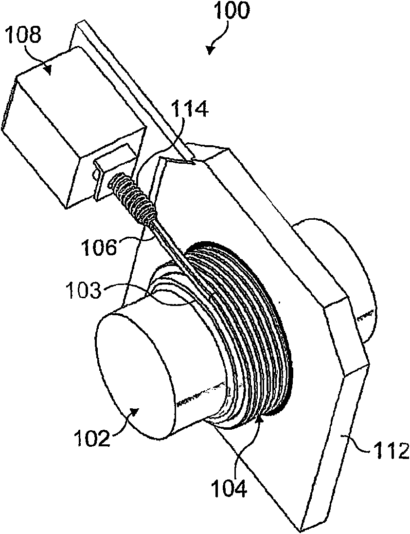
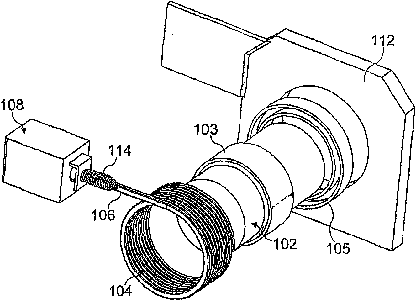
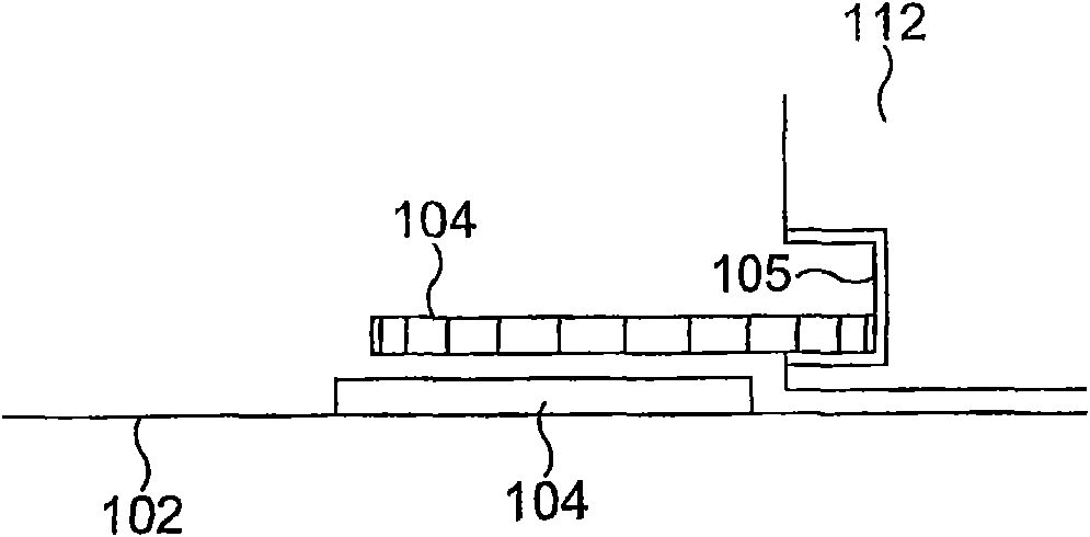
[0033] First refer to figure 1 and figure 2 , the braking device is generally indicated at 100 and includes a coil spring / torsion spring 104 mounted around an enlarged diameter portion 103 of a shaft 102 . The coil spring 104 has a coiled structure with a known relaxed diameter that is larger than the diameter of the enlarged diameter portion 103 so that under normal operating conditions there is a gap between the coil spring and the shaft 102 .

[0034] The inner end of the coil spring 104 is firmly anchored to the ring 105 or other anchor point separate from the shaft 102 . In this embodiment, ring 105 is formed on a portion of gearbox 112 (see figure 2 ).

[0035] In use, the solenoid 108 may be electrically controlled to tension the free end 106 of the coil spring 104 thereby tensioning the coil spring 104 around the shaft 102 . Once the control device 108 is energized, the action of the coil spring 104 is sufficient to retard or prevent rotation of the shaft 102 due...


PUM


Abstract

A wrap spring moves from a relaxed state to an energised state for braking rotation of the output shaft in a vehicle transmission. The wrap spring may constrict for engagement on the shaft or expand for engagement with an adjacent ground member. Two wrap springs, concentric (Figure 13) or axially spaced, provide bi-directional braking. A split ring energises both wrap springs, e.g. using an epicyclic differential arrangement to move opposing ring portions in opposite directions (Figure 11A). The wrap spring may be mounted in a relaxed state for rotation with the shaft, with a mechanism for inducing drag torque to energise the spring for a braking operation (Figure 12). Means is provided preventing an actuator from energising the wrap spring, e.g. if the shaft is rotating above a predetermined speed.

Description

technical field [0001] The present invention relates to a brake device, more specifically but not exclusively to a vehicle anti-rollback device and / or parking brake device. Background technique [0002] Vehicle rollback typically occurs when attempting to launch the vehicle from a standstill on an incline, especially if the vehicle has a dry clutch drivetrain. Pawl brakes are known to prevent movement of vehicles when parked, and these pawl brakes are used to prevent vehicles from rolling. However, these detents are not particularly durable during frequent part-load transitions, such as when launching on an incline. Contents of the invention [0003] It is an object of the present invention to provide an improved braking arrangement which reduces or prevents rolling back of the vehicle. [0004] According to one aspect of the present invention, there is provided a braking device comprising an output shaft and a wrap spring mounted around said shaft, wherein the wrap spri...

Claims


Application Information

Patent Timeline
Patent Type & Authority Applications(China)
IPC IPC(8): B60T1/06B60T7/12F16D41/20F16D13/02F16D27/105
CPCB60T1/062B60T7/122F16D49/04
Inventor J·威尔斯
Owner RICARDO UK LTD
Features
  • Generate Ideas
  • Intellectual Property
  • Life Sciences
  • Materials
  • Tech Scout
  • Unparalleled Data Quality
  • Higher Quality Content
  • 60% Fewer Hallucinations
Learn More