
Constant-pressure water supply device

A technology of constant pressure water supply and water inlet, which is applied in the configuration of water supply devices, water supply pools, and water saving, etc., can solve the problems of general adjustment effect, pressure fluctuation, and frequent switching of start and stop states of water supply pumps.

Inactive Publication Date: 2016-04-27
QINGDAO BOLIER MACHINERY EQUIP
View PDF0 Cites 2 Cited by
  • Summary
  • Abstract
  • Description
  • Claims
  • Application Information

AI Technical Summary

Problems solved by technology

However, in actual use, there are still many defects in this type of system, especially in systems with long or thin pipelines. The water pump stabilizes the water supply pressure by turning on or increasing the frequency. For flow water, there will be an obvious delay in the feedback of the water pressure signal to the controller, which will cause the phenomenon that the initial pressure is sufficient when the instantaneous large flow water is used, but the pressure is insufficient after a short time. Hysteresis brings about pressure fluctuations, especially when water is used at the end of a thinner pipe, such as the direct-connected flush valve of a common commercial building toilet. Stop state switching frequently
In similar water supply systems, in order to solve this problem, some places mostly use capsule-type air pressure tanks to adjust the pressure of the pipe network, and try to avoid pressure fluctuations caused by instantaneous water use and frequent start and stop of water pumps. It is not ideal, due to the limitation of the installation location, it is impossible to take into account all the water points. In addition, the air pressure tank itself has limited water adjustment, and the actual adjustment effect is average.

Method used


Image

  • Constant-pressure water supply device

Examples


Embodiment Construction

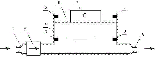
[0007] The working condition of this device is described below, figure 1 When the device is working, the water in the water supply pipe network enters the cavity (4) through the water inlet (1). The pressure generated is lower than the water supply pressure. At this time, the water level will rise until the top plate reaches the upper limit (5). When the water outlet connected to the water outlet (8) starts to use water, the water level in the cavity (4) will begin to drop, but Since the pressure generated by the counterweight (7) is a constant value, the water pressure in the cavity (4) will maintain this pressure and continue to supply water to the water outlet (8) until the top plate (6) drops to the lower limit (3 ) place. Thus, the water storage capacity provided by the device is fully utilized and the water supply is stabilized. After the water is finished, the top plate (6) will rise to the upper limit (5) again due to the water inlet pressure, so that the cavity (4) ...


PUM


Abstract

The invention provides a constant-pressure water supply device and aims to overcome the defects that when instant large-flow water use occurs at a water use terminal in a system with long or thin pipelines, water pressure signals fed back to a controller is evidently delayed, pressure fluctuation is generated, frequent on and off of a water-supply water pump in a short time occurs and the problems cannot be solved by a capsule type air pressure tank of a conventional water supply system. According to the technical scheme, a cavity with pressure stabilizing and water storing functions is designed, the cavity is communicated with a water supply pipe network and the water use terminal through a water inlet and a water outlet respectively, a check valve is arranged between the water inlet and the water supply pipe network, and the water in the pressure-stabilizing cavity can keep constant pressure through a counterweight structure. When the instant water use occurs at the water use terminal, stable-pressure water supply can be achieved by the cavity while severe fluctuation of the pressure at the water inlet end can be avoided by the cavity, and the pressure fluctuation of the water supply pipe network is eliminated.

Description

technical field [0001] The invention relates to a domestic water supply device, in particular to a device capable of maintaining constant pressure water supply under instantaneous large flow conditions. Background technique [0002] The current secondary domestic water supply is generally variable frequency and constant pressure water supply. By detecting the pressure change in the pipeline system to adjust the operating frequency of the water pump to achieve the function of constant water pressure. However, in the actual use process, there are still many defects in this type of system, especially in systems with long or thin pipelines, the water pump stabilizes the water supply pressure by turning on or increasing the frequency. For flow water, there will be an obvious delay in the feedback of the water pressure signal to the controller, which will cause the phenomenon that the initial pressure is sufficient when the instantaneous large flow of water is used, but the pressu...

Claims


Application Information

Patent Timeline
IPC IPC(8): E03B11/02
CPCY02A20/00
Inventor 张明亮张青华耿仁兵
Owner QINGDAO BOLIER MACHINERY EQUIP
Learn More