
LCD panel

A liquid crystal display panel and display area technology, applied in the direction of instruments, nonlinear optics, optics, etc., can solve the problems of affecting the appearance, different opening areas, and mismatching edge colors, so as to improve the appearance and visual comfort, and reduce the edge The effect of color mismatch

Active Publication Date: 2019-06-28
AU OPTRONICS CORP
View PDF5 Cites 0 Cited by
  • Summary
  • Abstract
  • Description
  • Claims
  • Application Information

AI Technical Summary

Problems solved by technology

[0003] However, in a display panel with a non-rectangular display area, the boundary between the display area and the frame area will cause the opening area of ​​each sub-pixel in a pixel to be different, so when displaying, it is easy to generate an edge (the display area and the frame area). area border) the problem of color mismatch, which affects the appearance

Method used


Image

  • LCD panel
  • LCD panel
  • LCD panel

Examples


Embodiment Construction

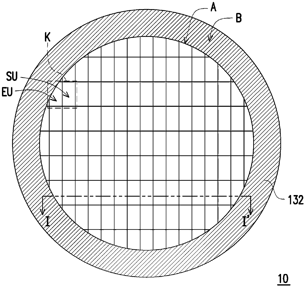
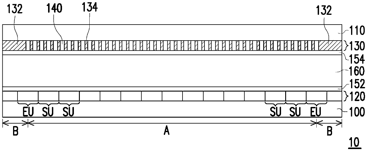
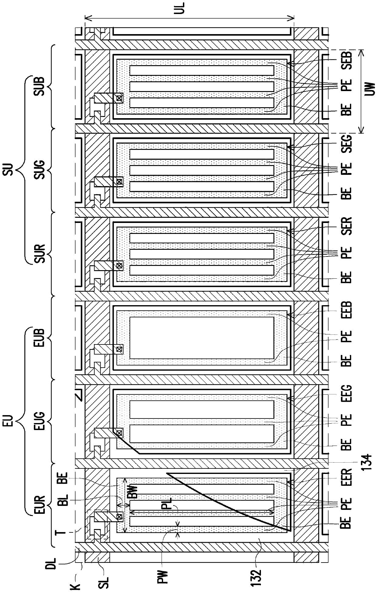
[0049] figure 1 is a schematic top view of a liquid crystal display panel according to an embodiment of the present invention. figure 2 is along figure 1 The cross-sectional schematic diagram of the section line I-I' in . image 3 yes figure 1 A schematic top view of area K of the first embodiment in FIG.

[0050] Please also refer to figure 1 and figure 2 , the liquid crystal display panel 10 has a display area A and a peripheral area B, wherein the peripheral area B surrounds the display area A. In detail, in this embodiment, the shape of the display area A is not a rectangle but a circle. However, the present invention is not limited thereto. In other embodiments, the shape of the display area A can also be any other regular or irregular shape, such as rhombus, ellipse, sector, egg, love heart, drop, etc., as long as it is not a rectangle.

[0051] The liquid crystal display panel 10 comprises an active matrix substrate 12, an opposite substrate 14 and a liquid cr...


PUM

PropertyMeasurementUnit
sizeaaaaaaaaaa

Abstract

The invention provides a liquid crystal display panel. The display panel comprises a first substrate, a peripheral light shielding layer, multiple standard pixels, multiple edge pixels, a second substrate and a liquid crystal layer. The peripheral light shielding layer is arranged in a peripheral region so that a display region is defined. The standard pixels are not overlapped with the peripheral light shielding layer. Each of the standard pixels comprises first, second and third standard pixel electrodes. The edge pixels and the peripheral light shielding layer are at least partially overlapped. Each of the edge pixels comprises first, second and third edge pixel electrodes. A pattern of at least one of the first, second and third edge pixel electrodes is different from a pattern of at least one of the first, second and third standard pixel electrodes. The second substrate is arranged in the opposite direction of the first substrate. The liquid crystal layer is arranged between the first substrate and the second substrate.

Description

technical field [0001] The invention relates to a display panel, and in particular to a liquid crystal display panel. Background technique [0002] In recent years, with the expansion of application fields, not only the requirements for properties such as thinness, narrow frame, and high image quality of display devices are increasing, but also the requirements for shape changes of the display area of ​​the display panel in the display device are also increasing. The shape of the display area of ​​a display device conventionally used in electronic equipment such as a TV, a personal computer, and a mobile phone is almost rectangular. The shape can no longer meet the needs of users. Therefore, these devices are usually equipped with display panels having non-rectangular display areas, such as circular or other shaped display areas. [0003] However, in a display panel with a non-rectangular display area, the boundary between the display area and the frame area will cause the...

Claims


Application Information

Patent Timeline
Patent Type & Authority Patents(China)
IPC IPC(8): G02F1/1343
CPCG02F1/134309
Inventor 朱育进
Owner AU OPTRONICS CORP
Learn More