LED display screen uniformity correction method

A technology of LED display and uniformity correction, applied in static indicators, instruments, etc., can solve problems such as low brightness and brightness loss, achieve uniform brightness and improve display effect.

Active Publication Date: 2016-04-27
XIAN NOVASTAR TECH
View PDF5 Cites 21 Cited by
  • Summary
  • Abstract
  • Description
  • Claims
  • Application Information

AI Technical Summary

Problems solved by technology

It is the implementation of the drive control that determines the inevitable loss of brightness after correction.
The current mainstream point-by-point correction method is the pulse width adjustment method, which is doomed to point-by-point correction must be "high pressure, low", and the loss of brightness after correction is inevitable, so that the overall brightness of the screen after correction is higher than that without correction. The overall brightness of the screen is low

Method used


Image

  • LED display screen uniformity correction method
  • LED display screen uniformity correction method
  • LED display screen uniformity correction method

Examples


no. 1 example

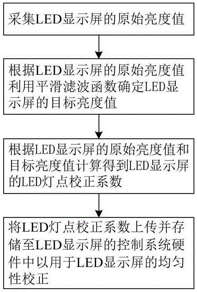
[0022] The method for correcting the uniformity of the LED display screen proposed by the first embodiment of the present invention is realized by the following steps, for example, and figure 1 Each step is shown in ; the LED display in this embodiment takes RGB full-color LED display as an example.

[0023] The first step is to collect the original brightness value of the LED display, specifically to control the LED display to display a variety of monochrome images in a preset order, that is, to display red (R) images, green (G) images and blue images in a preset order. Color (B) picture, wherein the red picture is formed by, for example, lighting up a plurality of red LED lamp points with the maximum brightness, and the green picture is formed, for example, by lighting up a plurality of green LED lamp points with the maximum brightness, and the blue picture is, for example, Formed by lighting multiple blue LED light spots at maximum brightness. And, in the process of displa...

no. 2 example

[0032] The method for correcting the uniformity of the LED display screen proposed in the second embodiment of the present invention is implemented by the following steps, for example. The LED display screen in this embodiment takes an RGB full-color LED display screen as an example.

[0033] The first step is to collect the original brightness value of the LED display, specifically to control the pure white picture of the LED display. formed by a blue LED light point. Moreover, in the process of displaying a pure white picture on the LED display screen, an image acquisition device such as a camera is used to capture the displayed pure white picture; and then the LED light of the LED display screen can be obtained by performing image processing on the captured pure white picture image. Point original brightness value, where the LED light point original brightness value refers to the original brightness value of each LED pixel point (typically composed of one RLED, one GLED and...


PUM


Abstract

The invention relates to an LED display screen uniformity correction method, which comprises the following steps: 1) collecting an original brightness value of an LED display screen; 2) determining a target brightness value of the LED display screen by utilizing a smoothing filtering function according to the original brightness value; 3) calculating LED light point correction coefficients of the LED display screen according to the difference between the target brightness value and the original brightness value; and 4) uploading and storing the LED light point correction coefficients to control system hardware of the LED display screen so as to carry out uniformity correction of the LED display screen. The method realizes brightness adjustment of the brightness value of each LED light point or pixel point of the LED display screen by adopting the smoothing filtering algorithm, so that the brightness of the whole screen is allowed to be uniform in vision, and the display effect of the LED display screen is greatly improved.

Description

technical field [0001] The invention relates to the technical field of LED display correction, in particular to a method for correcting the uniformity of an LED display screen. Background technique [0002] At present, LED display screens are more and more widely used indoors or outdoors. The LED display is a display screen that displays various information such as text, graphics, animation, video, and video signals by controlling semiconductor light-emitting diodes. The luminous brightness of LED (Light Emitting Diode, light-emitting diode) is determined by the luminous frequency. During use, due to the influence of manufacturing errors and aging phenomena, the luminous frequency of each LED light point is not completely consistent, which will cause LED display The overall brightness of the screen is uneven, pitting and mosaic appear, which seriously affects the display effect of the LED display. In order to improve the display effect of the display screen, uniformity cor...

Claims


Application Information

Patent Timeline
Patent Type & Authority Applications(China)
IPC IPC(8): G09G3/32
CPCG09G3/32G09G2320/0233
Inventor 杨城苏奕月李佳
Owner XIAN NOVASTAR TECH
Why Eureka
Try Eureka