Gas automatic water removal system

An automatic and gas technology, applied in the separation of dispersed particles, chemical instruments and methods, separation methods, etc., can solve problems such as manual replacement of condenser tubes by manpower, and achieve the effect of saving labor costs and improving accuracy

Inactive Publication Date: 2018-06-29
BEIJING HUAXIN SPACE & SKY TECH CO LTD
View PDF6 Cites 0 Cited by
  • Summary
  • Abstract
  • Description
  • Claims
  • Application Information

AI Technical Summary

Problems solved by technology

[0006] The purpose of the present invention is to provide an automatic gas dehydration system to solve the problem of manually replacing the condensate pipe after the inner wall of the condensate pipe is covered with ice in the traditional gas dewatering system in the field of greenhouse gas detection technology

Method used


Image

  • Gas automatic water removal system
  • Gas automatic water removal system
  • Gas automatic water removal system

Examples


Embodiment Construction

[0033] The present invention will be described in further detail below through specific implementation examples in conjunction with the accompanying drawings.

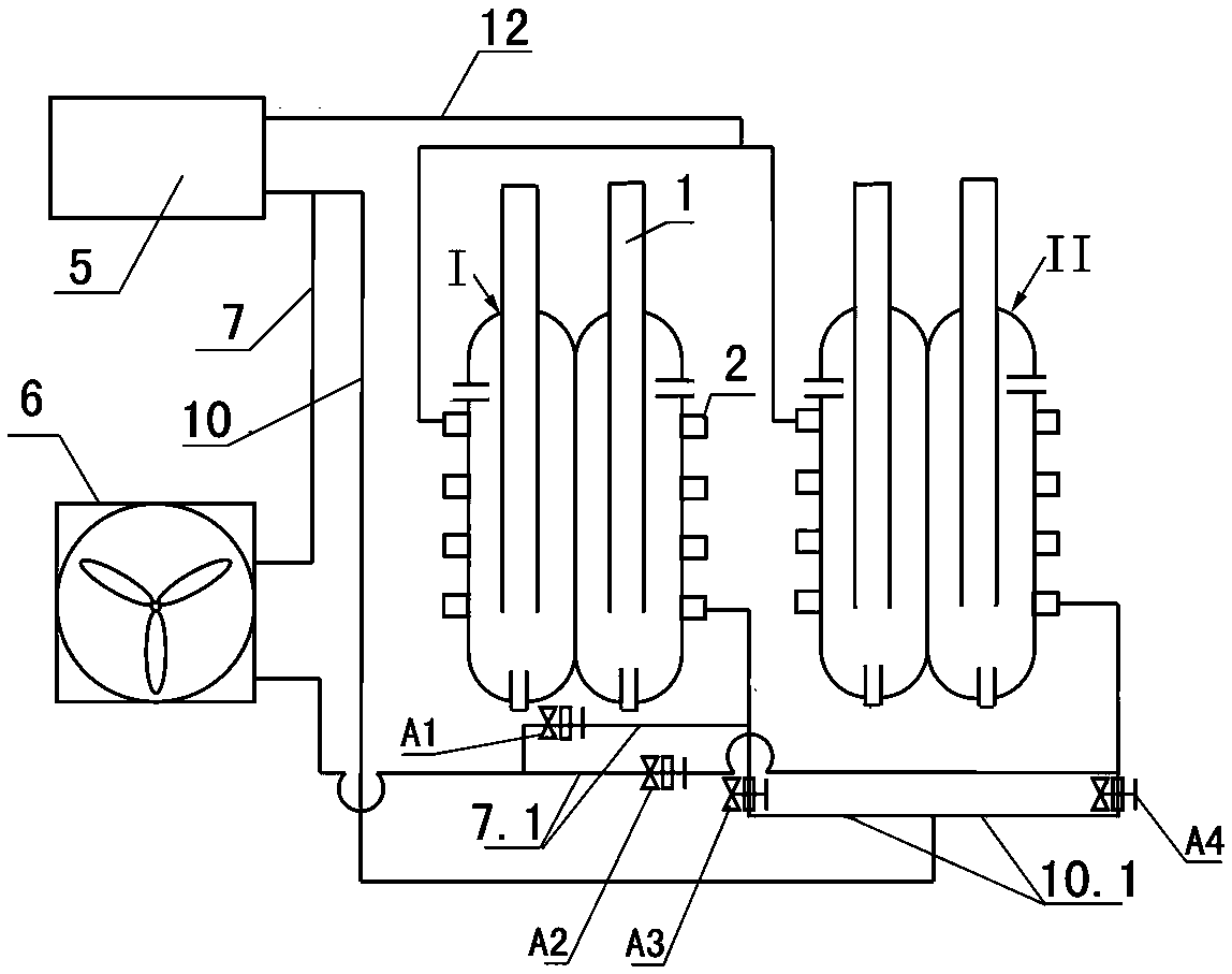
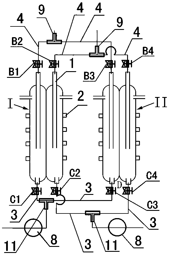
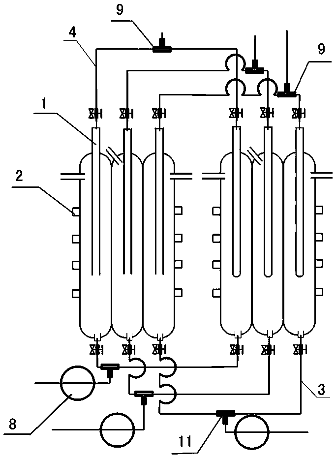
[0034] like figure 1 , figure 2 , Figure 5 As shown, in this embodiment, the gas automatic water removal system includes two sets of heat exchange modules and a drainage subsystem and an air outlet subsystem connected to the heat exchange modules.

[0035] Each set of heat exchange modules is provided with a refrigerant inlet, a refrigerant outlet, a gas path inlet and a gas path outlet, and the gas path outlet communicates with the air outlet subsystem.

[0036] The bottom of each group of heat exchange modules is provided with a drain, and the drain communicates with the drainage subsystem;

[0037] The gas automatic water removal system also includes a compressor 5 for heating the refrigerant and a condenser 6 for cooling the refrigerant;

[0038] The inlet of the compressor 5 communicates with the refrigerant...


PUM


Abstract

The invention relates to an automatic gas dewatering system, which comprises at least two groups of heat exchange modules, a water discharge sub system and a gas exhaust sub system, wherein the water discharge sub system and the gas exhaust sub system are communicated with the heat exchange modules; each group of heat exchange module is provided with a refrigerant inlet, a refrigerant outlet, a gas path inlet and a gas path outlet; the bottom of each group of heat exchange module is provided with a water discharge opening; the water discharge openings are communicated with the water discharge sub system; the automatic gas dewatering system also comprises a compressor for heating a refrigerant and a condenser for refrigerating the refrigerant; an inlet of the compressor is communicated with the refrigerant outlet of each group of heat exchange module through a refrigerant backflow pipeline; an outlet of the compressor is communicated with the refrigerant inlet of each group of heat exchange module through a first refrigerant pipeline and a second refrigerant pipeline in parallel arrangement. By using the scheme, ice formed in a condensing pipe can be automatically discharged after thawing; the manual replacement of the condensing pipe is not needed; the labor cost is reduced; gas to be detected can be continuously supplied; the precision of a gas detection value is improved.

Description

technical field [0001] The invention relates to an automatic gas water removal system, in particular to a gas automatic water removal system for continuous on-line gas monitoring and gas sampling in the technical field of greenhouse gas detection. Background technique [0002] In the prior art, the greenhouse gases in the atmosphere are generally monitored through a special gas monitoring system, through which the composition and content of the greenhouse gases can be accurately grasped, and then the greenhouse gases can be adjusted reasonably. However, since the greenhouse gas to be monitored contains a certain amount of water, the presence of water will inevitably affect the detection effect of the gas, making the detection value of the gas inaccurate. Therefore, before gas monitoring, it is necessary to remove water from the greenhouse gas so that the detected gas is a dry gas and improve the accuracy of the detection value. [0003] In the prior art, the FTS ultra-low t...

Claims


Application Information

Patent Timeline
Patent Type & Authority Patents(China)
IPC IPC(8): B01D53/26
CPCB01D53/265
Inventor 鲍诺巍
Owner BEIJING HUAXIN SPACE & SKY TECH CO LTD
Why Eureka
Try Eureka