A compound die for punching and cutting

A composite mold and ladder edge technology, applied in the direction of perforating tools, forming tools, manufacturing tools, etc., can solve the problems of slow work efficiency, many manufacturing processes, and complexity, so as to reduce manufacturing costs, reduce processing and manufacturing processes, and improve processing efficiency Effect

Active Publication Date: 2018-05-15
黄友华
View PDF7 Cites 0 Cited by
  • Summary
  • Abstract
  • Description
  • Claims
  • Application Information

AI Technical Summary

Problems solved by technology

In this way, there are many and complicated manufacturing processes; not only the work efficiency is slow, but also the cost is high; because of the many production processes, many people are employed; to modify the production process, supporting equipment and production sites are required; especially the flying saw is used to cut profiles and manually polish burrs The harsh noise that occurs will not only affect production, but also cause environmental pollution and safety issues for production personnel

Method used


Image

  • A compound die for punching and cutting
  • A compound die for punching and cutting
  • A compound die for punching and cutting

Examples


Embodiment Construction

[0029] In order to clearly illustrate the technical features of the solution, the solution will be described below through a specific implementation mode combined with the accompanying drawings.

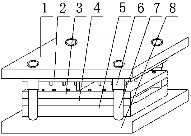
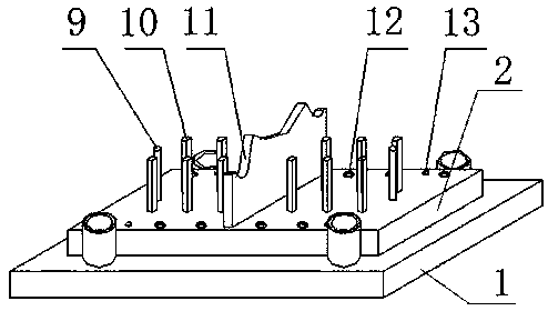
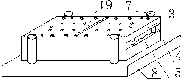
[0030] As can be seen from the accompanying drawings, a ladder edge punching composite mold includes an upper mold part, a lower mold part and a guide mechanism, and the upper mold part includes an upper mold frame plate 1 and an upper mold fixing plate 2, and the upper mold The fixed plate 2 is fixed with a punch and a punching upper knife 11, the middle part of the blade of the punching upper knife 11 is a concave first arc surface 23, and the two ends of the blade of the punching upper knife 11 are respectively The concave second arc surface 24, between the first arc surface 23 and the second arc surface 24 is a slope inclined from the middle to both ends; the lower mold part includes the lower mold frame plate 8 And the lower mold fixing plate 5, the lower mold fixing plate 5 is ...


PUM


Abstract

The invention provides a technical scheme of a combined die for terraced side punching. In the scheme, an upper die part comprises an upper die frame plate and an upper die fixing plate. A punch and an upper punching tool are fixed to the upper die fixing plate. The middle of the cutting edge of the upper punching tool is an inwards-concave first arc face. The two ends of the cutting edge of the upper punching tool are both inwards-concave second arc faces. A bevel inclining to the two ends from the middle is arranged between the first arc face and each second arc face. A lower die part comprises a lower die frame plate and a lower die fixing plate which is fixedly provided with two lower punching tools matched with the upper punching tool. The lower die fixing plate is provided with a punched hole and an upper punching tool guiding groove, and the punched hole and the upper punching tool guiding groove are matched with the punch and the upper punching tool. By using the combined die for terraced side punching, hole punching and cutting of a multi-curve-shaped terraced side can be completed at a time; due to the design of the cutting edge of the upper punching tool and the cutting edges of the lower punching tools, waste can easily fall out of a lower die after machining, and punching work efficiency is improved.

Description

technical field [0001] The invention relates to a mold, in particular to a ladder side punching composite mold. Background technique [0002] The ladder side is a relatively important component in the cable tray. It is connected with the ladder sections to form a ladder-shaped beam, which plays the role of a beam in the horizontally installed bridge. The side of the ladder is made of plates. In order to make it have a corresponding bearing capacity, it is artificially designed into a multi-curved section structure: one side is set as a hook-shaped side, the other side is a right-angle side, and two lines are added in the middle. Ribs. (This kind of structural shape is easy to deform, which makes it difficult to cut off) [0003] The traditional production method of the ladder side is: use the strip steel to go through the cold bending forming machine to produce the profile, and cut it off with the flying saw; then manually polish the burr (residual due to the cutting of th...

Claims


Application Information

Patent Timeline
Patent Type & Authority Patents(China)
IPC IPC(8): B21D37/10B21D28/14B21D28/34
CPCB21D28/14B21D28/34B21D37/10
Inventor 黄晶仇裕可王继增刘尚玉邱新民赵健波
Owner 黄友华
Why Eureka
Try Eureka