
Circulating cooling device for steel pipe

A circulating cooling and cooling device technology, applied in the field of steel pipe production equipment, can solve the problems of product quality decline, waste of water resources, uneven cooling of steel pipes, etc., and achieve the effect of preventing rust

Inactive Publication Date: 2016-05-04
天津建通管业有限公司
View PDF5 Cites 6 Cited by
  • Summary
  • Abstract
  • Description
  • Claims
  • Application Information

AI Technical Summary

Problems solved by technology

[0003] In view of this, the present invention aims to propose a steel pipe circulating cooling device to solve the technical problems of uneven cooling of steel pipes, decreased quality of finished products, and waste of water resources

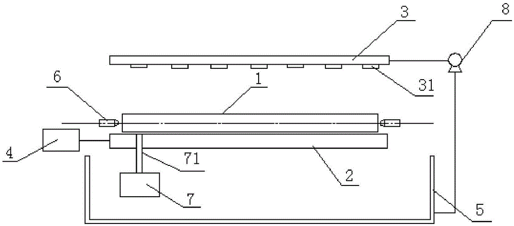
Method used


Image

  • Circulating cooling device for steel pipe

Examples


Embodiment Construction

[0013] The present invention will be described in detail below with reference to the accompanying drawings and examples.

[0014] Such as figure 1 As shown, a steel pipe circulating cooling device includes a support 2, a cooling water pipeline 3, a motor 4 and a water tank 5, and a drive roller and a driven roller connected to the water tank 5 outer motor 4 are arranged horizontally side by side in the support 2 (Fig. not shown), the steel pipe 1 is horizontally placed between the driving roller and the driven roller, the cooling water pipe 3 is arranged above the support 2, and the lower surface of the cooling water pipe 3 is uniformly provided with an upper spray head 31 , both ends of the steel pipe 1 are also provided with a horizontal nozzle 6, the axis of the horizontal nozzle 6 coincides with the axis of the steel pipe 1 for spraying water to the inner wall of the steel pipe 1, and a telescopic cylinder 7 is provided under one end of the support 1, The upper surface of...


PUM


Abstract

The invention provides a circulating cooling device for a steel pipe. The circulating cooling device for the steel pipe comprises a support (2), a cooling water pipeline (3), a motor (4) and a water tank (5). A driving roller and a driven roller which are connected with the motor (4) outside the water tank (5) are transversely arranged on the upper surface of the support (2) side by side. The cooling water pipeline (3) is arranged above the support (2). Upper spraying heads (31) are evenly arranged on the lower surface of the cooling water pipeline (3). A plurality of horizontal spraying heads (6) used for spraying water towards the inner wall of the steel pipe are arranged on the two sides of the support. According to the circulating cooling device for the steel pipe, the driving roller is used for driving the steel pipe to rotate, and the horizontal spraying heads are further arranged in the horizontal direction to be used for cooling the interior of the steel pipe so that the interior and the exterior of the steel pipe can be evenly cooled; in addition, the circulating cooling device is simple in structure and convenient to operate.

Description

technical field [0001] The invention relates to steel pipe production equipment, in particular to a steel pipe circulation cooling device. Background technique [0002] In the production process of seamless steel pipes, it is necessary to cool down the poured steel pipes in time. The commonly used cooling methods in the existing process include cold water cooling and natural cold air cooling. Natural cold air cooling has slow cooling time, low work efficiency and Disadvantages of the site occupying a large area. Most manufacturers will use cold water to cool the steel pipes. However, although the cold water cooling is sufficient, the performance of the steel pipes will decline due to the uneven spraying of cooling water, which cannot meet the factory requirements, resulting in a decrease in production costs. increase, but also cause a serious waste of water resources. Contents of the invention [0003] In view of this, the present invention aims to propose a steel pipe ci...

Claims


Application Information

Patent Timeline
IPC IPC(8): B22D30/00
CPCB22D30/00
Inventor 崔建国
Owner 天津建通管业有限公司
Learn More