Cotter assembling device

A block assembly and valve lock technology, which is applied in the field of auto parts, can solve the problems of high labor intensity for operators and low success rate of valve lock block assembly, and achieve high assembly efficiency, reduced labor intensity, and improved success rate.

Inactive Publication Date: 2016-05-04
CHONGQING CHANGAN AUTOMOBILE CO LTD
View PDF8 Cites 5 Cited by
  • Summary
  • Abstract
  • Description
  • Claims
  • Application Information

AI Technical Summary

Problems solved by technology

[0003] The Chinese patent with the publication number CN102179792A discloses a tool for installing and dismounting the engine valve lock block. In the middle, the operator has to keep pressing on the pull-and-press rod, and it relies on manpower to overcome the tension of the valve spring. The operator's operation is labor-intensive, resulting in a low success rate of valve lock block assembly.

Method used


Image

  • Cotter assembling device
  • Cotter assembling device
  • Cotter assembling device

Examples


Embodiment Construction

[0019] The present invention will be further described below in conjunction with accompanying drawing.

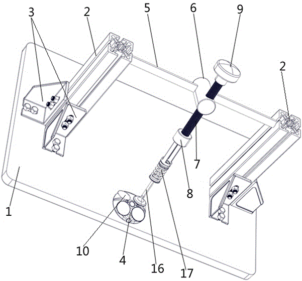
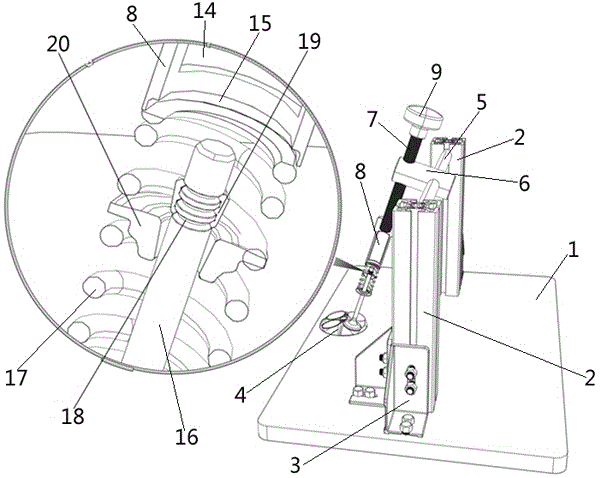
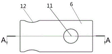
[0020] Such as figure 1 The valve lock block assembly device shown includes a base 1; the front side of the base 1 is provided with a valve support seat 4, and the valve support seat 4 is provided with a downward slope from front to back and / or a downward slope from back to front. The support platform 10, the left side and the right side of the base 1 are respectively provided with a support column 2, each support column 2 is fixed on the base 1 through two connection blocks 3, and the support column 2 and the connection block 3 are connected by bolts , the connection block 3 and the base 1 are connected by bolts, a slide bar 5 is arranged on the top of the base 1, the two ends of the slide bar 5 are respectively fixed on two supporting columns 2, and the slide bar 5 is provided with an adjusting slider 6 ,Such as image 3 with Figure 4 As shown, the rear portion of the...


PUM


Abstract

The invention relates to a cotter assembling device which comprises a base. An air valve supporting base is arranged on the front side of the base. A supporting platform is arranged on the air valve supporting base. The left side and the right side of the base are each provided with a supporting column. A sliding rod is arranged above the base. The two ends of the sliding rod are fixed to the two supporting columns respectively. The sliding rod is provided with an adjusting sliding block. The rear portion of the adjusting sliding block is provided with a through hole in clearance fit with the sliding rod. The front portion of the adjusting sliding block is provided with a threaded hole with the center axis perpendicular to the center axis of the through hole. A screw rod penetrating through the threaded hole is assembled in the threaded hole. A handle is arranged at the upper end of the screw rod. A press fitting sleeve is fixedly connected to the lower end of the screw rod. The lower end face of the press fitting sleeve is provided with a groove used for being matched with the air valve spring. The bottom of the groove is provided with a receding hole extending upwards. The side wall of the press fitting sleeve is provided with an observation hole communicated with the receding hole. By means of the cotter assembling device, the cotter assembling strength can be lowered, and the cotter assembling efficiency can be improved.

Description

technical field [0001] The invention relates to auto parts, in particular to an assembly device for a valve lock block. Background technique [0002] On a car engine, it is generally necessary to install and disassemble the valve lock block through a special device. When assembling the valve lock block, it is necessary to overcome the tension of the valve spring, compress the valve spring to a certain height and keep the compressed state unchanged, and at the same time use special tools to sequentially assemble the valve lock block into the corresponding ring groove of the valve stem, and then install the valve seat , and then loosen the valve spring, and the valve spring will tightly fit the valve lock block, valve seat and valve shaft together under the action of its own tension. The difficulty in assembling the valve lock block is that the valve spring must be compressed to a certain height and remain unchanged, which requires overcoming the strong tension of the valve s...

Claims


Application Information

Patent Timeline
Patent Type & Authority Applications(China)
IPC IPC(8): B25B27/14
CPCB25B27/14
Inventor 杨金利卢方军江宝宇谭莹罗通左云亮王鹏刘祖国
Owner CHONGQING CHANGAN AUTOMOBILE CO LTD
Why Eureka
Try Eureka