Magnetic stripe winding rolling machine
A magnetic strip and roll winding technology, which is applied in the directions of winding strips, thin material handling, transportation and packaging, etc., can solve the problems of high labor intensity, low degree of automation, and insufficient safety performance, so as to improve work efficiency and structure Simple, safe disassembly and assembly
- Summary
- Abstract
- Description
- Claims
- Application Information
AI Technical Summary
Problems solved by technology
Method used
Image
Examples
Embodiment 1
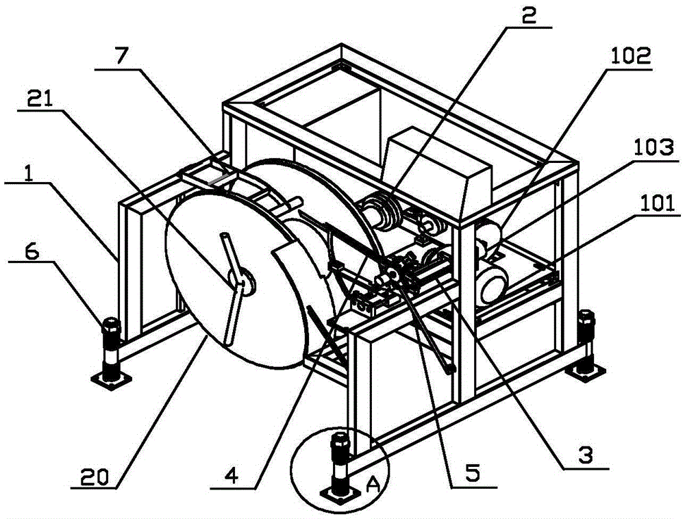
[0035] Such as figure 1 As shown, a magnetic strip winding machine includes a frame 1, the frame 1 is provided with a main shaft 2, the main shaft 2 is provided with a roller 20, and one side of the main shaft 2 is provided with a strip arrangement , the main shaft 2 and the strip arrangement device are all controlled by the PLC control system to realize the automatic arrangement of the magnetic strips around the rollers, effectively reducing the labor intensity and improving work efficiency.
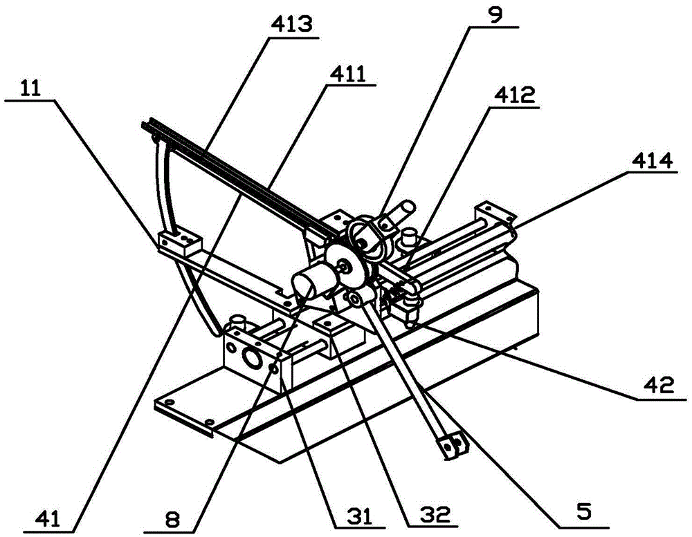
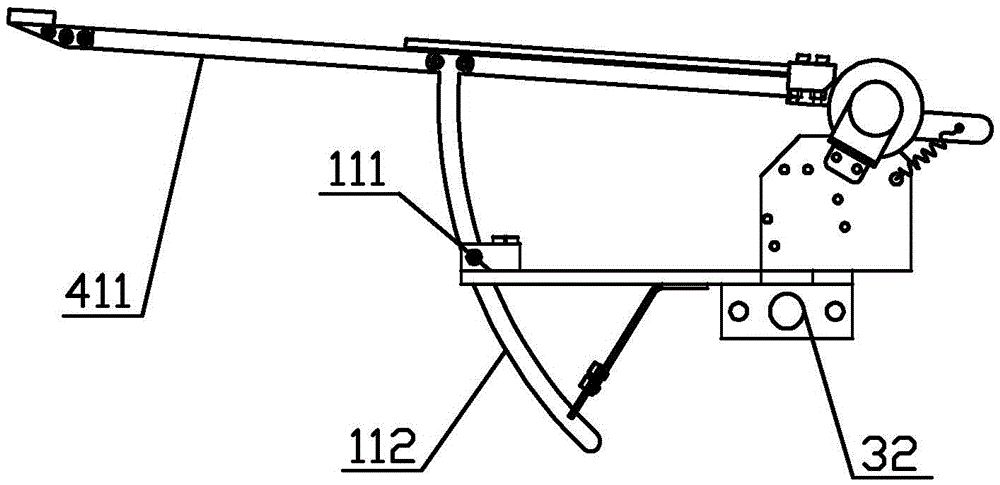
[0036] Such as figure 1 and figure 2 As shown, the strip arrangement device includes a lead screw moving mechanism 3, a broken bar stop mechanism 4 and a swing rod speed control mechanism 5, and the lead screw moving mechanism 3 includes a lead screw moving slide 31 and is arranged on a lead screw moving slide. The moving seat 32 on the track 31, the broken bar stop mechanism 4 and the swing rod speed control mechanism 5 are all arranged on the moving seat 32. The moving slideway 31...
Embodiment 2
[0041] Such as figure 2 and Figure 5 As shown, the strip arrangement device also includes a magnetic strip automatic meter counting device 8 and a pretensioning device 9, and the magnetic strip automatic meter counting device 8 includes a connected meter counting encoder 81 and a counting roller 82, and the counting roller 82 is provided with a groove 821, the pre-tensioning device 9 includes a connected anti-reverse roller 91 and a pre-tightening cylinder 92, the anti-reverse roller 91 is matched with the groove 821, in this embodiment, the anti-reverse The width of the anti-reverse roller 91 is smaller than that of the groove 821, and the anti-reverse roller 91 can be pre-tightened and fixed on the magnetic strip in the groove 821. Between the rods 41, the magnetic strip passes between the anti-reverse roller 91 and the counting roller 82 and is transmitted on the groove 821, and the pre-tightening cylinder 92 is activated to push the anti-reverse roller 91 to the countin...
Embodiment 3
[0046] Such as Figure 1-Figure 7 As shown, the working principle and process of a magnetic strip winding machine are as follows:
[0047] 1. First, manually pass the magnetic strip produced by the extruder through the magnetic strip limit end 511 on the swing rod 51, and introduce it into the magnetic strip guide track 413 on the row floating rod 41 through the groove 821 of the counting roller 82 , and then start the pre-tightening cylinder 92 to push the anti-reverse roller 91 into the groove 821 of the counting roller 82, and pre-tighten the magnetic strip;
[0048] 2. Manually install the empty roller 20 on the main shaft 2, and lock the roller 20 on the main shaft 2 through the locking device 21, and fix the magnetic strip drawn from the magnetic strip guide track 413 to the starting point of the roller 20. on the starting point;
[0049] 3. Start the magnetic strip winding machine, the PLC control system works to make the main shaft drive mechanism 101 drive the reduc...
PUM
 Abstract
Description
Claims
Application Information
 - R&D
- Intellectual Property
- Life Sciences
- Materials
- Tech Scout
- Unparalleled Data Quality
- Higher Quality Content
- 60% Fewer Hallucinations
Browse by: Latest US Patents, China's latest patents, Technical Efficacy Thesaurus, Application Domain, Technology Topic, Popular Technical Reports.
© 2025 PatSnap. All rights reserved.Legal|Privacy policy|Modern Slavery Act Transparency Statement|Sitemap|About US| Contact US: help@patsnap.com


