Wear-resisting anti-skidding lifting device of crane beam

A lifting device and crane technology, applied in the field of cranes and lifting devices, can solve the problems of waste materials in production and processing, short trolley beams, low labor efficiency, etc., achieve high mechanical strength and wear resistance, reduce production costs, and prolong service life Effect

Inactive Publication Date: 2016-05-04
ANHUI CHAOSHENG HOISTING MACHINERY CO LTD
View PDF0 Cites 0 Cited by
  • Summary
  • Abstract
  • Description
  • Claims
  • Application Information

AI Technical Summary

Problems solved by technology

[0003] In the crane production workshop, the position of the processed trolley beam is often moved or replaced. When moving the trolley beam, some lifting devices are often used to move the trolley beam. For the crane production workshop, the lifting device for moving the trolley beam is often used. A kind of shoulder pole lifting device, this kind of lifting device has a good lifting effect in function, but there are certain shortcomings in structure, mainly because the small car beam is relatively short, it does not need a large lifting device when lifting, and The shoulder pole lifting device is too large in size and complex in structure, which wastes materials in production and processing. In addition, it is complicated to fix the trolley beam when lifting the trolley beam, resulting in heavy workload and low labor efficiency. Therefore, it is necessary to develop a simple structure, low operating cost, Wear-resistant and anti-slip lifting devices for crane girders with high working efficiency and comprehensive functions are of great significance

Method used


Image

  • Wear-resisting anti-skidding lifting device of crane beam
  • Wear-resisting anti-skidding lifting device of crane beam

Examples


Embodiment 1

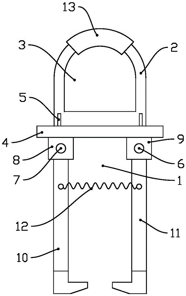
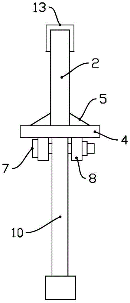
[0018] see Figure 1~2 In an embodiment of the present invention, a wear-resistant and anti-slip lifting device for a crane girder includes a lifting device body 1, a lifting plate 2 is provided on the upper part of the lifting device body 1, and a lifting plate 2 is sleeved at the middle position of the top of the lifting plate 2. Grinding sheath 13, the lifting plate 2 is provided with a lifting hole 3, the lower end of the lifting plate 2 is provided with a connecting plate 4, and the connection between the lifting plate 2 and the connecting plate 4 is provided with a reinforcing plate 5, and the reinforcing plate 5 It is a triangular structure, and the left and right parts of the lower side of the connecting plate 4 are respectively connected with a hook bracket A8 and a hook bracket B9. The hook bracket A8 is connected with a hook A10, the hook A is connected with the hook bracket A8 through a bolt A7, the hook bracket B9 is connected with a hook B11, and the hook B11 is ...

Embodiment 2

[0021] see Figure 1~2 In an embodiment of the present invention, a wear-resistant and anti-slip lifting device for a crane girder includes a lifting device body 1, a lifting plate 2 is provided on the upper part of the lifting device body 1, and a lifting plate 2 is sleeved at the middle position of the top of the lifting plate 2. Grinding sheath 13, the lifting plate 2 is provided with a lifting hole 3, the lower end of the lifting plate 2 is provided with a connecting plate 4, and the connection between the lifting plate 2 and the connecting plate 4 is provided with a reinforcing plate 5, and the reinforcing plate 5 It is a triangular structure, and the left and right parts of the lower side of the connecting plate 4 are respectively connected with a hook bracket A8 and a hook bracket B9. The hook bracket A8 is connected with a hook A10, the hook A is connected with the hook bracket A8 through a bolt A7, the hook bracket B9 is connected with a hook B11, and the hook B11 is ...


PUM


Abstract

The invention discloses a wear-resisting anti-skidding lifting device of a crane beam. The wear-resisting anti-skidding lifting device comprises a lifting device body, wherein a lifting plate is arranged on the upper part of the lifting device body; a wear-resisting sheath is arranged on the middle position of the top part of the lifting plate in a sleeving mode; a lifting hole is formed in the lifting plate; the lower end of the lifting plate is provided with a connecting plate; a joint of the lifting plate and the connecting plate is provided with a reinforcing plate; the left part and the right part of the lower side surface of the connecting plate are respectively connected with a hanger bracket A and a hanger bracket B; the hanger bracket A and the hanger bracket B are bilaterally symmetrical structures which are matched; the hanger bracket A is connected to a hanger A; the hanger A is connected to the hanger bracket A through a bolt A; the hanger bracket B is connected to a hanger B; the hanger B is connected to the hanger bracket B through a bolt; the hanger A and the hanger B are bilaterally symmetrical structures which are matched; and the hanger A and the hanger B are connected through a spring. The wear-resisting anti-skidding lifting device has the advantages of being simple in structure, low in operation cost, high in working efficiency and complete in function.

Description

technical field [0001] The invention belongs to the technical field of production equipment, in particular to a lifting device, in particular to a crane [0002] Beam wear-resistant anti-slip lifting device. Background technique [0003] In the crane production workshop, the position of the processed trolley beam is often moved or replaced. When moving the trolley beam, some lifting devices are often used to move the trolley beam. For the crane production workshop, the lifting device for moving the trolley beam is often used. A kind of shoulder pole lifting device, this kind of lifting device has a good lifting effect in function, but there are certain shortcomings in structure, mainly because the small car beam is relatively short, it does not need a large lifting device when lifting, and The shoulder pole lifting device is too large in size and complex in structure, which wastes materials in production and processing. In addition, it is complicated to fix the trolley beam...

Claims


Application Information

Patent Timeline
Patent Type & Authority Applications(China)
IPC IPC(8): B66C1/10
CPCB66C1/10
Inventor 王云祥
Owner ANHUI CHAOSHENG HOISTING MACHINERY CO LTD
Why Eureka
Try Eureka