
A super calender

A super calender and calender roller technology, applied in the field of papermaking equipment, can solve many problems in the processing and operation process, calender rollers collide with each other, large calender rollers and paper guide rollers, etc., to achieve movement space changes Small, less intermediate problems, smooth motion effect

Active Publication Date: 2017-04-26
ZIBO TAIDING MASCH TECH CO LTD
View PDF6 Cites 0 Cited by
  • Summary
  • Abstract
  • Description
  • Claims
  • Application Information

AI Technical Summary

Problems solved by technology

However, this structure makes the calender rollers do a swinging motion in the vertical direction. During the movement, the center of the calender rollers is not in the same vertical plane, resulting in a large change in the spatial position of the calender rollers. more problems
Moreover, the diameter of the calender roller will change due to wear and tear during use, which will cause the relative position of the calender roller and the paper guide roller to change, which will affect the effect of calendering and paper guide.
[0004] Chinese utility model patent ZL201320297415.0 discloses a multi-roll calender. The balance oil cylinder balances the gravity of the calender rolls through the swing arm hinged on the frame. Points do circular arc movement, the movement space of the calender rolls changes greatly, and the calender rolls are prone to collide with each other during the rapid roll separation and fast roll closing process, which will damage the calender rolls
This method of gravity balance using the swing arm type is a technical misunderstanding in the structural design of the super calender, and in the improvement of the super calender, it has not been able to solve the large movement space of the calender roller and the calender roller and guide paper. Technical solution to the problem that the relative position of the rollers will change

Method used


Image

  • A super calender
  • A super calender
  • A super calender

Examples


Embodiment Construction

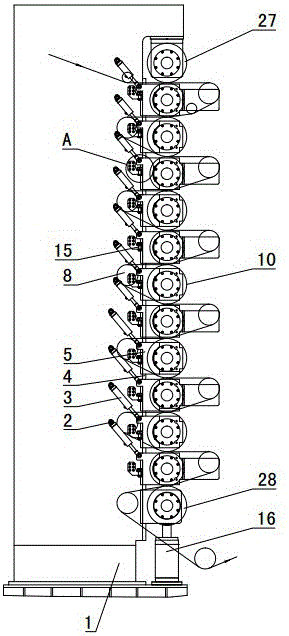
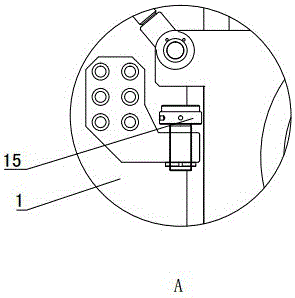
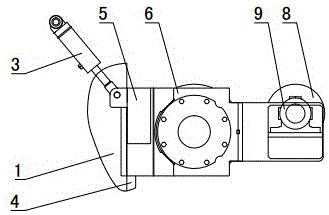
[0044] Figure 1~16 It is the best embodiment of the present invention, below in conjunction with attached Figure 1~16 The present invention will be further described.

[0045] A super calender, comprising a frame 1, on which a vertical guide mechanism is arranged, a calender roller 10 and a paper guide roller 8 are slidably connected to the guide mechanism through a sliding seat 5, and the frame 1 is provided with a For the gravity balance system that balances the gravity of the calender rolls 10, a bottom pressing device is provided under the lowermost calender roll 10, and the bottom pressing device pushes each calender roll 10 up and presses the calender roll 10 , The calender roll 10 is quickly off the roll under the action of gravity. The gravity balance system of the super calender can balance the weight of the calender roll 10, so that the pressure of the lower nip and upper nip of the super calender on the paper web can be controlled, and the difference between the...


PUM


Abstract

The invention discloses a super calender and belongs to the technical field of papermaking equipment. The super calender comprises a machine frame and is characterized in that a vertical guiding mechanism is arranged on the machine frame (1); calendering rollers (10) and paper guiding rollers (8) are in sliding connection with the guiding mechanism through a slide base (5); the machine frame (1) is provided with a gravity balancing system used for balancing the gravity of the calendering rollers (10); a bottom pressurizing device is arranged below the calendering roller (10) at the lowermost end, pushes the calendering rollers (10) to ascend and is used for pressurizing the calendering rollers (10); the calendering rollers (10) are fast released under the action of gravity. The gravity balancing system on the super calender can be used for balancing the weight of the calendering rollers so that pressure of a lower pressing region and an upper pressing region of the super calender on paper web is controllable, and two-side difference of the paper web is accurately controlled; the calendering rollers moves along a straight line through the guiding mechanism, the movement space of the calendering rollers slightly changes, and intermediate problems in the processing and operating process are few.

Description

technical field [0001] A super calender belongs to the technical field of papermaking equipment. Background technique [0002] In paper production, the calender is the key equipment that ultimately determines the quality of the paper. For a long time, high-grade cultural papers such as coated paper, super matt paper and special industrial technical paper have been finished on existing super calenders. Multiple calender rollers of the super calender are arranged vertically. Due to the influence of the calender roller’s own weight, the line pressure of each nip gradually increases from top to bottom, resulting in a large difference in the quality index of the two sides of the paper after calendering, which hinders the quality of the paper. The improvement of the grade affects the printing speed and printing effect. [0003] In addition, the calender rolls of existing super calenders are all controlled by oil cylinders through swing arms to balance the gravity of the calender...

Claims


Application Information

Patent Timeline
Patent Type & Authority Patents(China)
IPC IPC(8): D21G1/00D21G1/02
CPCD21G1/004D21G1/0086D21G1/0293
Inventor 诸葛宝钧宋懿贞任山吴保海马东浩王坤杨光
Owner ZIBO TAIDING MASCH TECH CO LTD
Learn More