
Device and method for measuring displacement of object in paramagnetic box based on magnetic mark

A technology of magnetic marking and object displacement, applied in the direction of measuring devices, using electrical devices, using electromagnetic means, etc., can solve human health hazards, X-rays have weak penetrating ability to metal boxes, and the measurement of small displacements of objects in boxes is rare and other problems to achieve the effect of overcoming the difficulty of penetrating metal and high measurement accuracy

Active Publication Date: 2016-05-04
MATERIAL INST OF CHINA ACADEMY OF ENG PHYSICS
View PDF5 Cites 2 Cited by
  • Summary
  • Abstract
  • Description
  • Claims
  • Application Information

AI Technical Summary

Problems solved by technology

[0003] At present, X-ray imaging or γ-ray detection technology is generally used to detect objects in the box. Among them, X-ray imaging technology is widely used in the field of security inspection and medical field. The former pays more attention to the shape, structure and other information of the objects in the box, while the latter Pay more attention to the images and pathology of human organs and tissues, but the penetration ability of X-rays to metal boxes is weak, and it is rare to measure the small displacement of objects in the box
The γ-ray is more harmful to human health, so it is more used for material flaw detection, but strictly speaking, the γ-ray has little damage to the material.
In addition, although gamma rays have strong qualitative measurement capabilities for defects, it is also difficult to quantitatively measure small displacements of objects

Method used


Image

  • Device and method for measuring displacement of object in paramagnetic box based on magnetic mark
  • Device and method for measuring displacement of object in paramagnetic box based on magnetic mark
  • Device and method for measuring displacement of object in paramagnetic box based on magnetic mark

Examples


Embodiment Construction

[0038] The present invention will be further described below with reference to the accompanying drawings and embodiments, and the mode of the present invention includes but not limited to the following embodiments.

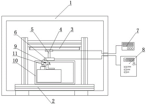
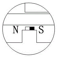
[0039] Such as figure 1 , 2 As shown, the present invention provides a displacement measuring device, which can be applied to non-destructive testing. The device includes a magnetic shielding room 1, a gantry-type measuring frame 2, a magnetic marker 9, a first measuring system and a second measuring system.

[0040] The magnetic shielding room 1 adopts a double-layer permalloy magnetic shielding room (for example, a double-layer 1.5mm permalloy magnetic shielding room), which can shield the earth's magnetic field to below 10 milligauss under the environment of the earth's magnetic field of 0.5 gauss. The gantry-type measuring frame 2 is arranged in the magnetic shielding room 1, and a paramagnetic box 10 loaded with a measured object 11 is placed therein. In th...


PUM


Abstract

The invention discloses a device for measuring the displacement of an object in a paramagnetic box based on a magnetic mark, and the device comprises a magnetic shielding room, a gantry type measurement rack, the magnetic mark, a first measurement system, and a second measurement system. The gantry type measurement rack is disposed in the magnetic shielding room, and the interior of the gantry type measurement rack is provided with the paramagnetic box containing the measured object. The magnetic mark is fixed at a part, nearest to the internal surface of the paramagnetic box, of the measured object, and is magnetized in a possible displacement direction of the measurement object. The first measurement system is used for recording the magnetic field changes before and after the placement of the measured object and the magnetic field change after the measured object moves. The second measurement system is used for carrying out corresponding one-dimensional coordinate calibration when the first measurement system records the magnetic field changes. The device achieves the no-damage detection of the displacement of the object in a paramagnetic metal or nonmetal box, is higher in detection depth, is lower in error, causes no damage to materials and human bodies, and is suitable for popularization and application.

Description

technical field [0001] The invention relates to the field of non-destructive testing, in particular to a device for measuring the displacement of an object in a paramagnetic box based on a magnetic mark and a measuring method thereof. Background technique [0002] In the field of non-destructive testing, the detection of objects in the box is a common application, such as the detection of relative displacement and misalignment of parts in the product packaged in the box, especially when the box cannot be easily disassembled or disassembled. This non-destructive testing is necessary when damage is done. [0003] At present, X-ray imaging or γ-ray detection technology is generally used to detect objects in the box. Among them, X-ray imaging technology is widely used in the field of security inspection and medical field. The former pays more attention to the shape and structure of the objects in the box, while the latter More attention is paid to the images and pathology of hu...

Claims


Application Information

Patent Timeline
Patent Type & Authority Applications(China)
IPC IPC(8): G01B7/02
CPCG01B7/02
Inventor 刘政豪朱康伟刘静徐庆东
Owner MATERIAL INST OF CHINA ACADEMY OF ENG PHYSICS
Learn More