Zero-magnetic-flux shallow transient electromagnetic test coil and test method thereof

A transient electromagnetic and testing coil technology, used in radio wave measurement systems, measurement devices, and electrical/magnetic exploration, etc., can solve problems such as signal distortion of the receiving coil, reduce the size of the coil, improve the signal-to-noise ratio and detect Depth, the effect of increasing the emitted magnetic moment

Active Publication Date: 2019-08-30
ANHUI UNIV OF SCI & TECH
View PDF15 Cites 10 Cited by
  • Summary
  • Abstract
  • Description
  • Claims
  • Application Information

AI Technical Summary

Problems solved by technology

[0010] Aiming at the deficiencies of the prior art, the purpose of the present invention is to provide a zero-flux shallow transient electromagnetic test coil and its test method, which solves the secondary field mixing induced by the primary field and the shallow detection target in the prior art. Overlapping, resulting in technical problems of signal distortion in the receiving coil

Method used


Image

  • Zero-magnetic-flux shallow transient electromagnetic test coil and test method thereof
  • Zero-magnetic-flux shallow transient electromagnetic test coil and test method thereof
  • Zero-magnetic-flux shallow transient electromagnetic test coil and test method thereof

Examples


Embodiment 1

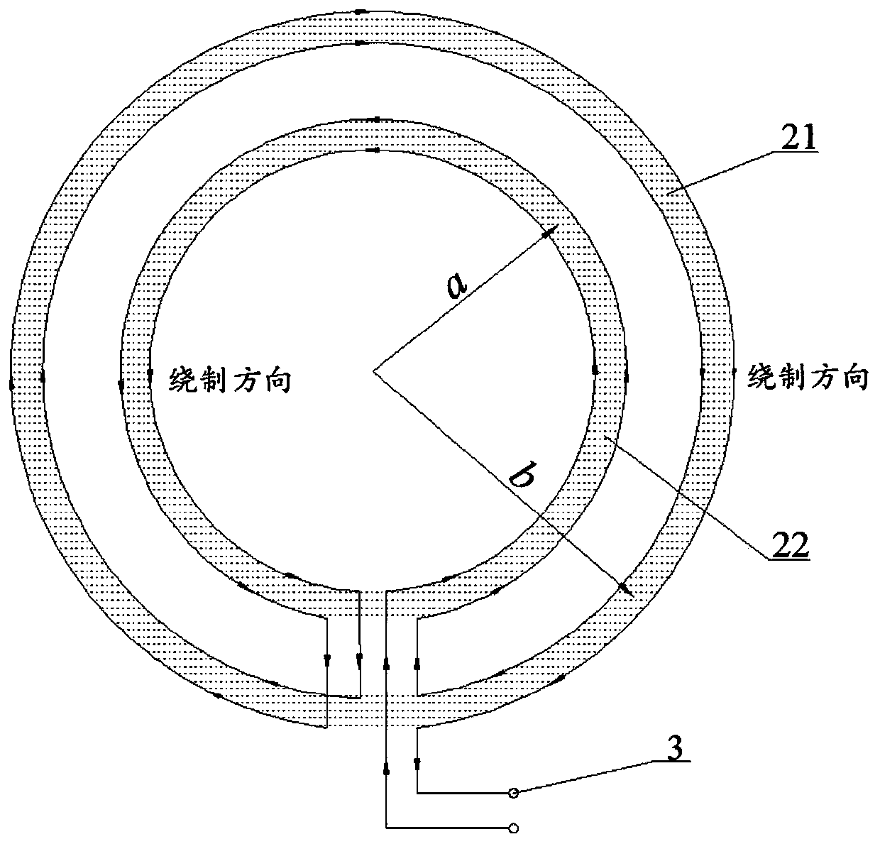
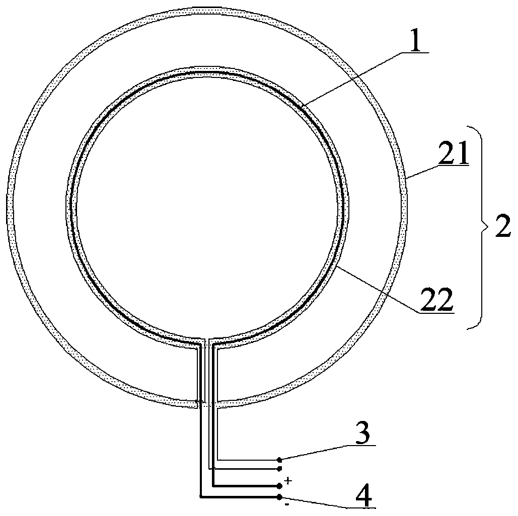
[0042] Such as figure 1 As shown, this embodiment provides a zero-flux shallow transient electromagnetic test coil, including a transmitting coil 1 and a receiving coil 2, and the transmitting coil 1 and the receiving coil 2 are nested with each other, wherein the receiving coil 2 includes an outer receiving coil 21 and The inner receiving coil 22 has two parts, the radius of the inner receiving coil 22 is equal to the radius of the transmitting coil 1, the radius of the outer receiving coil 21 is greater than the radius of the inner receiving coil 22, and the transmitting coil 1 and the receiving coil 2 are coplanar and coaxially arranged, and the outer receiving coil The number of turns of 21 is greater than the number of turns of the inner receiving coil 22, and the internal turns of the transmitting coil 1 and the receiving coil 2 are connected in series.

[0043]By adjusting the relative positional relationship between the transmitting coil 1 and the receiving coil 2, the...

Embodiment 2

[0075] Such as Figure 4 As shown, this embodiment provides a zero-flux shallow transient electromagnetic test coil. Compared with Embodiment 1, on the premise that the overall structure remains the same, the shapes of the transmitting coil 1 and the receiving coil 2 are changed, such as being designed as a rectangle. A current-carrying coil device, but it is necessary to ensure that the radius and the number of turns of the transmitting coil 1 , the outer receiving coil 21 and the inner receiving coil 22 satisfy a specific ratio relationship.

[0076] The test coil winding method of embodiments 1 and 2, the operation steps are as follows:

[0077] 1) Wind the transmitting coil 1 clockwise (counterclockwise) with a radius a for several turns.

[0078] 2) The receiving coil 2 is wound one turn counterclockwise (clockwise) with the same radius a to form the inner receiving coil 22, and then expanded to the radius b and wound one turn clockwise (counterclockwise) to form the out...


PUM


Abstract

The invention discloses a zero-magnetic-flux shallow transient electromagnetic test coil and a test method thereof. The test coil comprises a transmitting coil and a receiving coil, wherein the transmitting coil is embedded in the receiving coil and is arranged in a coplanar and coaxial manner; the receiving coil comprises an outer receiving coil and an inner receiving coil; the radius of the outer receiving coil is larger than that of the inner receiving coil; the radius of the inner receiving coil is equal to that of the transmitting coil; and meanwhile, the turns inside the transmitting coil and the receiving coil are connected with each other in series. By the test method provided by the invention, the primary fields in the inner receiving coil and the outer receiving coil are equal insize and opposite in direction, and mutually offset to enable the total magnetic flux in the receiving coil to be zero, so that the effective elimination of the primary fields is realized, a pure secondary field signal is obtained, the shallow detection blind area range is greatly reduced, and the transient electromagnetic shallow detection resolution is effectively improved.

Description

technical field [0001] The invention belongs to the technical field of geophysical transient electromagnetic detection, and in particular relates to a zero-flux shallow transient electromagnetic test coil and a test method thereof. Background technique [0002] Transient electromagnetic method (TEM) is an important method in geophysical exploration. It uses an ungrounded loop to send a pulsed electromagnetic field underground, and uses a coil to observe the spatial and temporal distribution of the secondary electromagnetic field generated by the underground eddy current induced by the primary pulsed electromagnetic field. , so as to solve the time-domain electromagnetic method for geological problems. [0003] With the rapid development of urban infrastructure construction, reservoir dam detection and railway highways, it is particularly important for the exploration of shallow geological problems. Considering the limitation of the construction site conditions, the solution...

Claims


Application Information

Patent Timeline
Patent Type & Authority Applications(China)
IPC IPC(8): G01V3/10
CPCG01V3/105
Inventor 胡雄武孟当当肖玉林
Owner ANHUI UNIV OF SCI & TECH
Why Eureka
Try Eureka