
Thermal infrared imager variable power in-place mechanism and thermal infrared imager

An infrared thermal imager and position-limiting technology, which is applied in the direction of instruments, scientific instruments, measuring devices, etc., can solve the problems of difficult zoom control, large space occupation, and low efficiency, and achieve convenient and quick adjustment, convenient operation, and continuous Adjustment effect

Inactive Publication Date: 2016-05-04
LUOYANG INST OF ELECTRO OPTICAL EQUIP OF AVIC
View PDF6 Cites 4 Cited by
  • Summary
  • Abstract
  • Description
  • Claims
  • Application Information

AI Technical Summary

Problems solved by technology

This zoom in place mechanism not only cannot realize the stepless and continuous adjustment of the zoom position, but also needs to install and disassemble the gasket and adjust the position for each zoom, which makes the whole zoom process less efficient
[0003] In the prior art, there is also a zoom in place mechanism that directly controls the field of view zoom frame to be in place through a tension spring. This mechanism is mainly suitable for double field of view zoom adjustments. In the case of multi-field zoom adjustments, the mechanism There are problems such as the large space occupied by the axial direction of the zoom, the complicated zoom mechanism, and the difficulty in realizing the zoom control.

Method used


Image

  • Thermal infrared imager variable power in-place mechanism and thermal infrared imager
  • Thermal infrared imager variable power in-place mechanism and thermal infrared imager
  • Thermal infrared imager variable power in-place mechanism and thermal infrared imager

Examples


Embodiment Construction

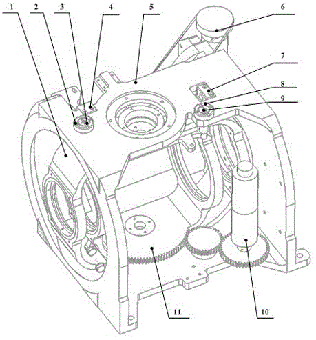
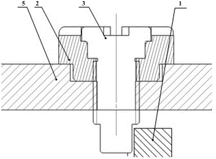
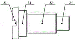
[0024] The thermal imaging camera in Embodiment 1 of the present invention is a thermal imaging camera with three fields of view, and the thermal imaging camera has a small field of view, a middle field of view and a large field of view. Such as Figure 1 to Figure 7 As shown, the infrared thermal imager includes a variable magnification in place mechanism, and the magnification in place mechanism includes a base 5 and a field of view variable magnification frame that is located in the base and can be screwed in and out of the base along the front and rear directions. There are two groups of magnification frames, which are the large field of view zoom frame 1 and the medium field of view zoom frame 11. The large field of view zoom frame 1 is connected to the large field of view driving element 6, and the large field of view driving element 6 can drive the large field of view. The zoom frame is screwed into and out of the base; the middle field of view zoom frame 11 is connecte...


PUM


Abstract

The present invention relates to a thermal infrared imager variable power in-place mechanism and a thermal infrared imager. The thermal infrared imager variable power in-place mechanism comprises a pedestal and a field variable power frame being located in the pedestal and being capable of screwing in and out the pedestal in the back and forth direction; the pedestal is provided with a spacing adjustment knob capable of stop cooperating with the back and forth of the field variable power frame to perform spacing of the field variable power frame; the spacing adjustment knob is provided with at least one length of reducer with a gradually changed turning radius of an outer periphery; and the field variable power frame is subjected to variable power in place while being stop cooperating with the reducer. Compared with a setting extension spring structure in the prior art, the thermal infrared imager variable power in-place mechanism solves the technical problem that the occupation space of the thermal infrared imager variable power in-place mechanism is large in the prior art, a spacing adjustment knob is able to limit the degree of freedom of the rotation direction of a variable power frame, and the rotation of a reducer is able to realize non-limited variable power and continuous adjustment, so that the adjustment is more convenient and rapid.

Description

technical field [0001] The invention relates to a variable magnification in place mechanism of an infrared thermal imager and an infrared thermal imager. Background technique [0002] Multi-field infrared thermal imaging cameras are widely used in photoelectric detection equipment in airborne / shipborne and other fields. The multi-field infrared thermal imager has a zoom mechanism. At present, the working principle of the multi-field infrared thermal imager’s zoom mechanism is: the adjustment screw adjusts the zoom frame of the field of view by increasing or decreasing the shim. Location. The magnification in place mechanism not only cannot realize the stepless and continuous adjustment of the magnification position, but also needs to install and disassemble the shim and adjust the position for each magnification change, which makes the efficiency of the whole magnification process low. [0003] In the prior art, there is also a zoom mechanism that directly controls the zoo...

Claims


Application Information

Patent Timeline
Patent Type & Authority Applications(China)
IPC IPC(8): G01J5/08
CPCG01J5/084G01J5/07
Inventor 郭向硕吴健伟
Owner LUOYANG INST OF ELECTRO OPTICAL EQUIP OF AVIC
Learn More