
Electric appliance mold box mounting structure

A technology of installation structure and mold box, which is applied in the direction of supporting machines, connecting components, electrical components, etc., can solve the problems of difficult disassembly and assembly by maintenance personnel or users, increased labor intensity of maintenance personnel, and decreased user experience of users, etc., to achieve convenience Disassembly, improve stability, avoid interference effect

Pending Publication Date: 2022-01-21
成都博轩家具有限公司
View PDF0 Cites 0 Cited by
  • Summary
  • Abstract
  • Description
  • Claims
  • Application Information

AI Technical Summary

Problems solved by technology

[0005] When it is necessary to repair or replace the electrical module box, it is necessary to remove the electrical module box and the panel as a whole before repairing the internal components of the electrical module box; because the panel is often heavy, it is difficult for maintenance personnel or users to disassemble Larger, which increases the labor intensity of maintenance personnel and reduces the user experience of users

Method used


Image

  • Electric appliance mold box mounting structure
  • Electric appliance mold box mounting structure
  • Electric appliance mold box mounting structure

Examples


Embodiment 1

[0045] see figure 1 , image 3 , Figure 6~Figure 8 .

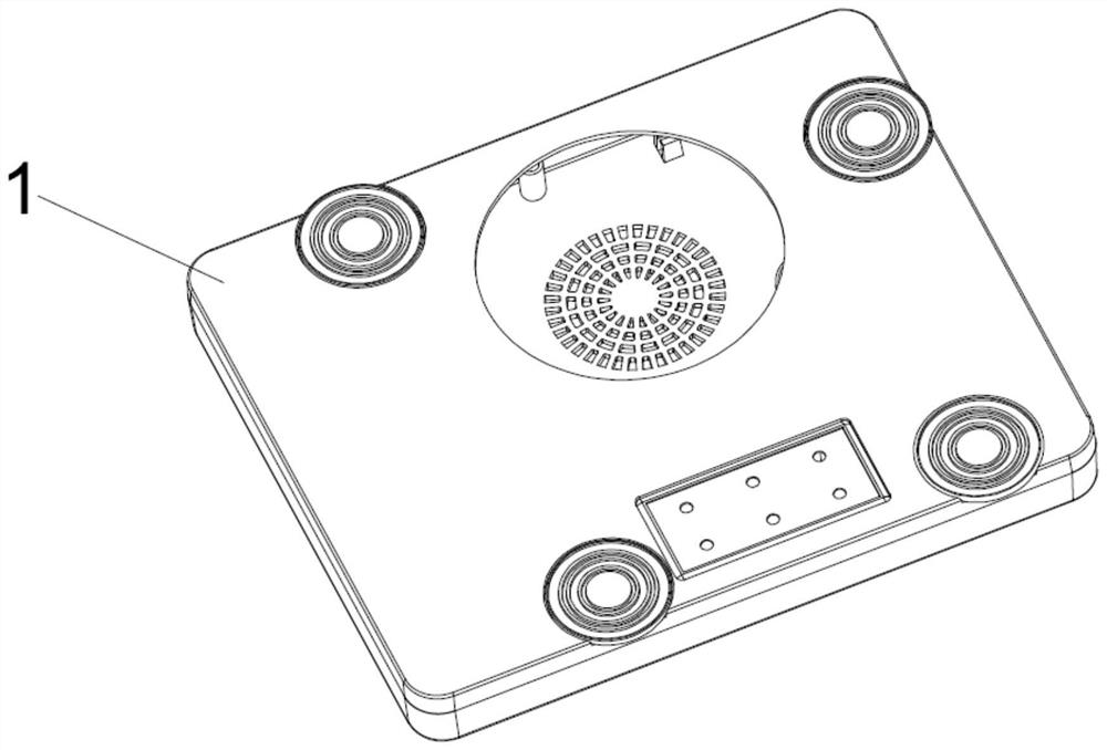
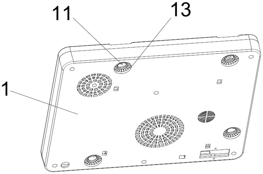
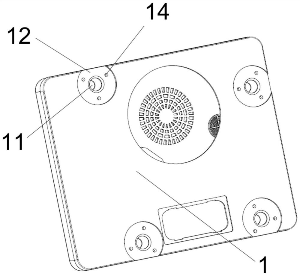
[0046] An electrical module box installation structure is provided for realizing the connection between the electrical module box body 1 and the panel 4, the installation structure passes through the electrical module box body 1, and the panel 4 can be directly operated on the surface of the panel 4 on the electrical module box body 1 The panel of touch screen, as glass panel etc.; The corresponding position of the touch screen is provided with an operation hole.

[0047] The installation structure includes mushroom nails, the top of the mushroom nails is fixedly connected to the panel 4, and the installation structure also includes a locking support that can cooperate with the mushroom nails to lock the electrical module box;

[0048] When the locking support is separated from the mushroom nail, the electrical module box body 1 is separated from the mushroom nail;

[0049] When the locking support is locked with the...

Embodiment 2

[0068] see Figure 1~5 , Figure 7 , Figure 9 and Figure 10 .

[0069] The arrangement of mushroom nails and locking support members in Embodiment 1 will cause the following problems:

[0070] In order to ensure the disassembly and assembly of the electrical module body 1 of different sizes, that is, the thickness, the second stud 61 needs to reserve a longer length. When there are some parts that need to move relative to the electrical module body 1 in the use area (such as Drawers, etc.), the second stud 61 and the locking support located outside the electrical module body 1 will interfere with the relative moving parts, making the installation structure unable to adapt to the use area, that is, the applicability of the installation structure will be subject to special use area impact.

[0071] The difference from Example 1 is:

[0072] The mushroom nail includes a mushroom head 21 connected to the panel 4 and a mushroom rod 22 located inside the electrical module bo...


PUM


Abstract

The invention discloses an electric appliance mold box mounting structure which comprises mushroom nails, electric appliance mold box body molds of different sizes can be quickly disassembled and assembled through the mounting structure, and when components in the electric appliance mold box body molds are damaged, a user only needs to independently disassemble the electric appliance mold box body mold and mails the electric appliance mold box body mold to an after-sales service department for replacement or maintenance, the electric appliance mold box body mold and the panel mold do not need to be integrally disassembled and mailed, the workload of after-sales service personnel is relieved, and meanwhile the user experience is improved; the further optimized mounting structure avoids the situation that the electric appliance module box body interferes with the relatively moving parts, and the application scene of the mounting structure is expanded.

Description

technical field [0001] The invention relates to the technical field of furniture production, in particular to an installation structure of an electrical mold box. Background technique [0002] The existing electrical module box installation method is: [0003] First, brush the top surface of the electrical module box with an adhesive such as glue, then bond it to the panel where the items are placed, and finally install the panel and the electrical module box as a whole to the use area (such as the top area of ​​the bedside table, the desktop panel area, etc.). [0004] Since the components inside the electrical mold box of furniture products are often damaged, the existing installation method will cause the following problems: [0005] When it is necessary to repair or replace the electrical module box, it is necessary to remove the electrical module box and the panel as a whole before repairing the internal components of the electrical module box; because the panel is oft...

Claims


Application Information

Patent Timeline
Patent Type & Authority Applications(China)
IPC IPC(8): H05K5/02F16M11/04F16B37/00F16B35/06
CPCH05K5/0217F16M11/04F16B35/06F16B37/00
Inventor 王礼登
Owner 成都博轩家具有限公司
Learn More