
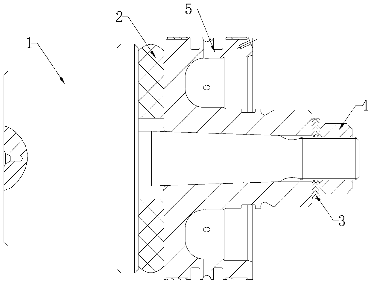
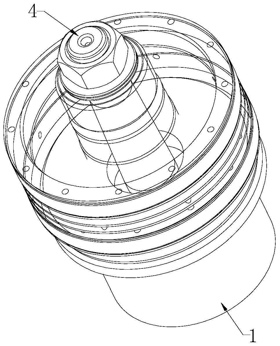
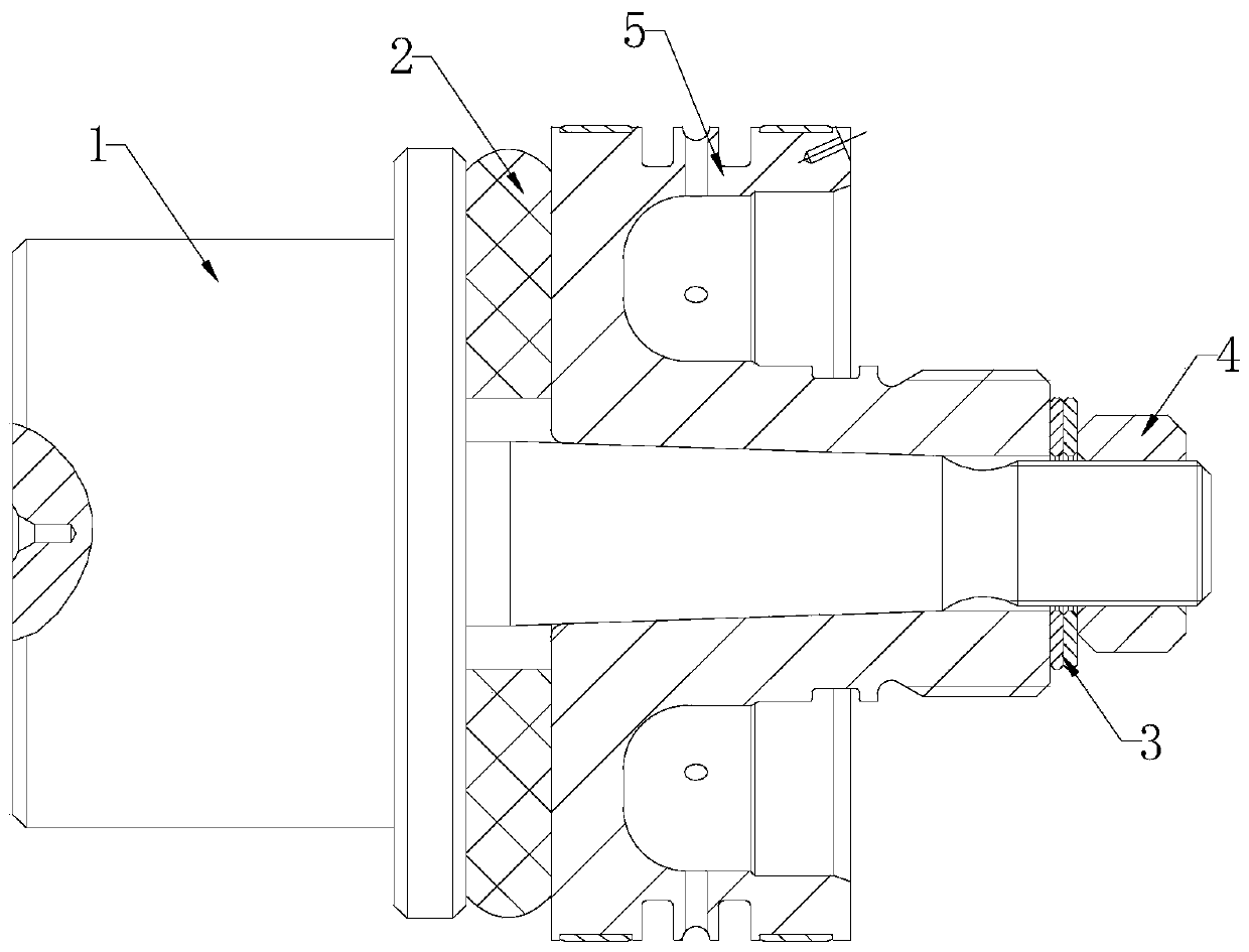
Workpiece self-centering elastic removal device

A self-centering, workpiece technology, applied in positioning devices, metal processing machinery parts, manufacturing tools, etc., can solve the problems of not too tight fit, low processing efficiency, easy to damage the mandrel, etc., to achieve convenient operation and high reliability , high efficiency effect

Pending Publication Date: 2020-05-12
ZHONGCHUAN NO 9 DESIGN & RES INST
View PDF0 Cites 0 Cited by
  • Summary
  • Abstract
  • Description
  • Claims
  • Application Information

AI Technical Summary

Problems solved by technology

[0002] The traditional mandrel tapered surface locates the workpiece, there is no workpiece ejection device, and it cannot be too tightly matched. After the process is completed, the main body mandrel and the workpiece need to be taken out of the machine tool, and then the workpiece and the main body mandrel are placed on the workbench. Separated, resulting in the defects of low processing efficiency, easy damage to the workpiece, and easy damage to the mandrel; in addition, because the fit cannot be too tight, the friction between the workpiece and the mandrel is not enough to limit the degree of freedom of rotation, so it can only be used for cutting force Smaller cylindrical turning and cylindrical grinding cannot be used for milling the outer contour surface of the workpiece or drilling or boring the end face hole or radial hole of the workpiece

Method used


Image

  • Workpiece self-centering elastic removal device
  • Workpiece self-centering elastic removal device
  • Workpiece self-centering elastic removal device

Examples


Embodiment Construction

[0015] The technical solutions in the embodiments of the present invention will be clearly and completely described below with reference to the accompanying drawings in the embodiments of the present invention. Obviously, the described embodiments are only a part of the embodiments of the present invention, but not all of the embodiments. Based on the embodiments of the present invention, all other embodiments obtained by those of ordinary skill in the art without creative efforts shall fall within the protection scope of the present invention.

[0016] In the description of the present invention, it should be noted that the orientations or positional relationships indicated by the terms "vertical", "upper", "lower", "horizontal", etc. are based on the orientations or positional relationships shown in the drawings, only In order to facilitate the description of the present invention and simplify the description, it is not indicated or implied that the indicated device or elemen...


PUM


Abstract

The invention belongs to the technical field of mechanical engineering, and particularly discloses a workpiece self-centering elastic removal device. The workpiece self-centering elastic removal device comprises a body mandrel installed on a machine tool, the body mandrel is sequentially provided with an elastic removal pad, a flat gasket and a gland nut, the gland nut is in threaded connection with the body mandrel, a virtual workpiece is installed in a cavity between the elastic removal pad and the flat gasket, and fixing of the virtual workpiece is achieved. Compared with the prior art, theworkpiece self-centering elastic removal device can be installed on machine tools such as a lathe, a milling machine, a machining center and a grinding machine, based on the friction force between the body mandrel and the conical surface of the workpiece as well as the friction force formed between the elastic removal pad and the end surface of the workpiece, the rotational degree of freedom canbe limited, the workpiece self-centering elastic removal device can be widely applied to polyhedron turning, milling, drilling and the like of various parts positioned through a conical surface hole as well as workpiece outline surface milling or workpiece end surface hole drilling or radial hole drilling and machining of other work surfaces, and the workpiece self-centering elastic removal devicehas the advantages of being high in efficiency, precision and reliability and convenient to operate.

Description

technical field [0001] The invention relates to the technical field of mechanical engineering, in particular to a workpiece self-centering elastic withdrawal device. Background technique [0002] The traditional mandrel taper surface locates the workpiece, there is no workpiece withdrawal device, and the fit cannot be too tight. After the process is completed, the body mandrel and the workpiece need to be taken out from the machine tool, and then the workpiece and the body mandrel are placed on the worktable. separation, resulting in the defects of low processing efficiency, easy damage to the workpiece, and easy damage to the mandrel; in addition, because the fit cannot be too tight, the friction between the workpiece and the mandrel is not enough to limit the rotational freedom, so it can only be used for cutting force Smaller external turning and external grinding cannot be used for milling the outer contour surface of the workpiece or for drilling and boring the end hole...

Claims


Application Information

Patent Timeline
IPC IPC(8): B23Q3/12
CPCB23Q3/12
Inventor 陈文云孙路王辉宇钱蔚鑫彭娟吕崇升
Owner ZHONGCHUAN NO 9 DESIGN & RES INST
Learn More