Motor control and protection switch with overload thermal memory protection function

A protection function and protection switch technology, applied in the direction of emergency protection circuit devices, electrical components, etc., can solve the problems of motor insulation damage, burnout, shortening the service life of the motor, etc., and achieve the effect of prolonging the service life and avoiding burnout

Inactive Publication Date: 2016-05-04
WUXI WING DUOPULI TECH CO LTD
6 Cites 0 Cited by

AI-Extracted Technical Summary

Problems solved by technology

When the temperature inside the motor rises to the maximum allowable temperature, it will cause the motor insulation to be damaged and burnt
It can be seen that although the single-chip microcomputer is used to realize the on and off of the switch through the protec...

Abstract

The invention discloses a motor control and protection switch with an overload thermal memory protection function. The motor control and protection switch comprises a motor, a three-phase switch, an overload thermal memory module, a first current transformer, a second current transformer and a third current transformer, wherein input ends of the first current transformer, the second current transformer and the third current transformer are connected with three phase lines of a three-phase power supply respectively; output ends of the first current transformer, the second current transformer and the third current transformer all are connected with three-phase terminals of the motor through the switch respectively; control ends of the first current transformer, the second current transformer and the third current transformer are connected with corresponding input ends of the overload thermal memory module; and the output end of the overload thermal memory module is connected with the three-phase switch by virtue of a wire. By the motor control and protection switch with the overload thermal memory protection function, the burnout condition that the motor is insulated and damaged due to a temperature rise can be avoided; the service lifetime of the motor is prolonged; and the motor control and protection switch can be used for preventing the motor from being damaged due to an over-high temperature.

Application Domain

Technology Topic

Memory protectionPhase lead +7

Image

  • Motor control and protection switch with overload thermal memory protection function
  • Motor control and protection switch with overload thermal memory protection function

Examples

  • Experimental program(1)

Example Embodiment

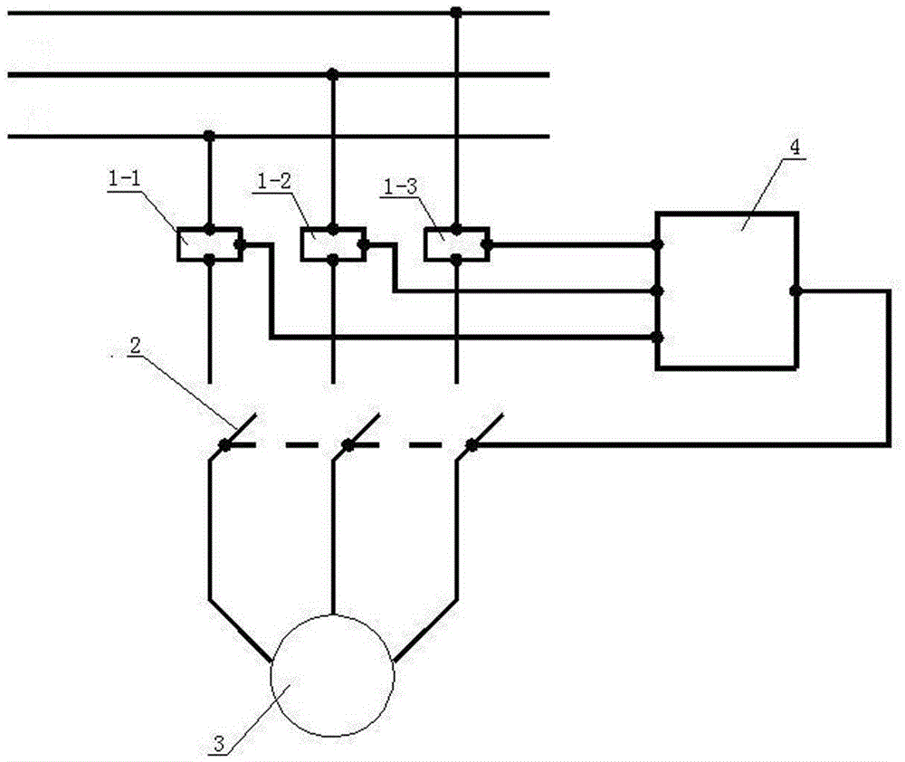
[0011] Such as figure 1 As shown, the motor control and protection switch with overload thermal memory protection function of the present invention includes a motor 3, a three-phase switch 2, an overload thermal memory module 4, a first current transformer 1-1, and a second current transformer 1-2 And the third current transformer 1-3, the input terminals of the first current transformer 1-1, the second current transformer 1-2 and the third current transformer 1-3 are respectively connected to the three phase lines of the three-phase power supply , The output ends of the first current transformer 1-1, the second current transformer 1-2, and the third current transformer 1-3 are all connected to the three-phase terminals of the motor through switches, and the first current transformer 1-1 The control terminals of the second current transformer 1-2 and the third current transformer 1-3 are respectively connected to the corresponding input terminals of the overload thermal memory module 4, and the output terminal of the overload thermal memory module 4 is connected to the three-phase switch 2 by means of wires. .
[0012] Such as figure 2 As shown, the overload thermal memory module 4 includes a single-chip microcomputer MCU, a first unit module, a second unit module, and a third unit module. The input terminals of the first unit module, the second unit module and the third unit module are respectively connected to the first unit module. The control terminals of the current transformer 1-1, the second current transformer 1-1 and the third current transformer 1-3 are connected, and the output terminals of the first unit module, the second unit module and the third unit module are respectively connected to the The corresponding input terminals of the MCU are connected. The first unit module, the second unit module and the third unit module all contain an operational amplifier U1 and a diode D1. The positive input terminal of the operational amplifier U1 is connected to the ground through a third resistor R3, and the negative input terminal of the operational amplifier U1 is connected to the ground. There are a first resistor R1, a second resistor R2, and a first capacitor C1. The first resistor R1 and one end of the first capacitor C1 are connected together as the input terminal of the corresponding unit module and connected to the ground. The other end of the capacitor C1 is connected to the cathode of the input terminal of the operational amplifier U1 through the second resistor R2; the cathode of the diode D1 is connected to the output terminal of the operational amplifier U1, and the anode of the diode D1 is connected through the fifth resistor R5 and the second capacitor C2 is connected to the ground, the connection point of the fifth resistor R5 and the second capacitor C2 is connected to the corresponding input terminal of the MCU; the connection point of the anode of the diode D1 and the fifth resistor R5 is connected to the negative input of the operational amplifier U1 Indirectly there is a fourth resistor R4.
[0013] During operation, the current in the three phase wires is sent to the overload thermal memory module 4 through the first current transformer 1-1, the second current transformer 1-2 and the third current transformer 1-3. 4 Judge the temperature by calculating the change of current and time. If the temperature determined by the overload thermal memory module 4 is too high, it outputs a trip signal to the switch to power off the motor 3.

PUM

no PUM

Description & Claims & Application Information

We can also present the details of the Description, Claims and Application information to help users get a comprehensive understanding of the technical details of the patent, such as background art, summary of invention, brief description of drawings, description of embodiments, and other original content. On the other hand, users can also determine the specific scope of protection of the technology through the list of claims; as well as understand the changes in the life cycle of the technology with the presentation of the patent timeline. Login to view more.

Similar technology patents

Classification and recommendation of technical efficacy words

  • Extended service life
  • Avoid burning
Why Eureka
Try Eureka