Rotor Core Assemblies, Rotor Assemblies and Motors

A rotor core and assembly technology, applied in the direction of electric components, magnetic circuit rotating parts, electromechanical devices, etc., can solve problems such as failure to achieve better bonding strength, difficulty in ensuring assembly concentricity, and affecting the magnetic performance of the motor. The assembly concentricity is easy to guarantee, the structure is firm and reliable, and the effect of small vibration

Active Publication Date: 2019-03-01
GUANGDONG WELLING ELECTRIC MACHINE MFG
View PDF4 Cites 0 Cited by
  • Summary
  • Abstract
  • Description
  • Claims
  • Application Information

AI Technical Summary

Problems solved by technology

[0002] In the motor in the related art, in order to ensure the magnetic permeability and dynamic balance performance, the fit gap between the rotor core and the magnetic ring is small, so when the rotor core and the magnetic ring are bonded, the gap remaining in the fit gap Adhesive materials (such as glue) are limited and cannot achieve good bond strength
If the fit gap is increased to ensure the amount of bonding material, the air gap between the magnetic ring and the rotor core will be too large, which will affect the magnetic performance of the motor. The surrounding surfaces are all circumferential surfaces, and the large fit gap between the two circumferential surfaces is difficult to ensure the assembly concentricity, resulting in eccentricity of the rotor assembly, excessive dynamic balance, and finally large vibration of the motor

Method used


Image

  • Rotor Core Assemblies, Rotor Assemblies and Motors
  • Rotor Core Assemblies, Rotor Assemblies and Motors
  • Rotor Core Assemblies, Rotor Assemblies and Motors

Examples


Embodiment Construction

[0029] Embodiments of the present invention are described in detail below, examples of which are shown in the drawings, wherein the same or similar reference numerals designate the same or similar elements or elements having the same or similar functions throughout. The embodiments described below by referring to the figures are exemplary only for explaining the present invention and should not be construed as limiting the present invention.

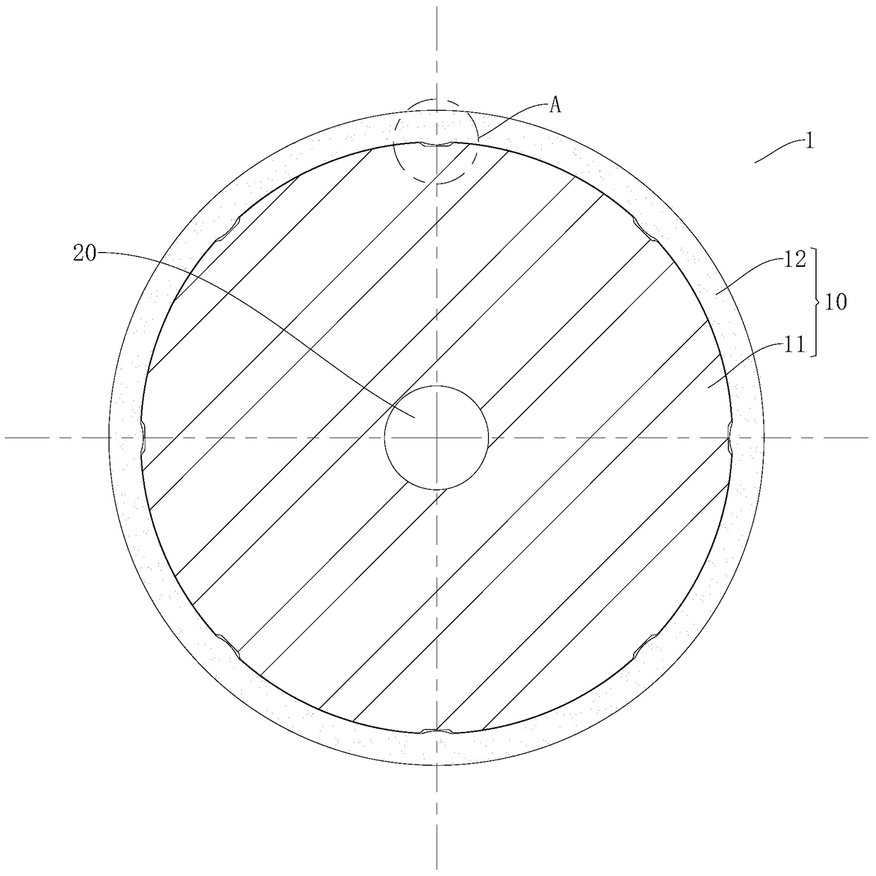
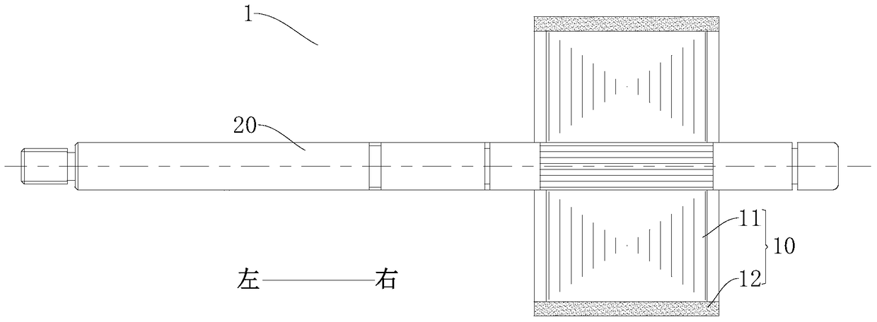
[0030] Refer below Figure 1-Figure 3 The rotor core assembly 10 according to the embodiment of the first aspect of the present invention is described. The rotor core assembly 10 can achieve better bonding strength and ensure magnetic permeability and dynamic balance performance.

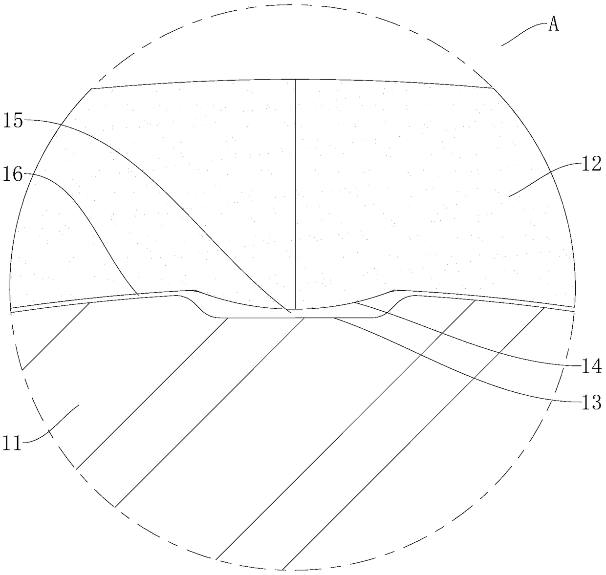
[0031] Such as Figure 1-Figure 3 As shown, the rotor core assembly 10 according to the embodiment of the present invention includes a rotor core 11 and a magnetic ring 12 .

[0032] Specifically, at least one of the inner peripheral surface of the magnetic ...


PUM


Abstract

The invention discloses a rotor core component, a rotor assembly with the same and a motor with the rotor assembly. The rotor core component comprises a rotor core and a magnetic ring; a bonding groove is formed in at least one of the inner circumference of the magnetic ring and the outer circumference of the rotor core; the magnetic ring sleeves the rotor core; and an adhesive material is filled between the inner circumference of the magnetic ring and the outer circumference of the rotor core. The rotor core component disclosed by the invention can reach relatively good bonding degree and ensure the permeability and the dynamic balance performance.

Description

technical field [0001] The invention relates to the technical field of motors, in particular to a rotor core assembly, a rotor assembly with the rotor core assembly and a motor with the rotor assembly. Background technique [0002] In the motor in the related art, in order to ensure the magnetic permeability and dynamic balance performance, the fit gap between the rotor core and the magnetic ring is small, so when the rotor core and the magnetic ring are bonded, the gap remaining in the fit gap The amount of bonding material (such as glue) is limited, and a good bonding strength cannot be achieved. If the fit gap is increased to ensure the amount of bonding material, the air gap between the magnetic ring and the rotor core will be too large, which will affect the magnetic performance of the motor. The circumferential surfaces are all circumferential surfaces, and the large fit gap between the two circumferential surfaces is difficult to ensure the concentricity of assembly,...

Claims


Application Information

Patent Timeline
Patent Type & Authority Patents(China)
IPC IPC(8): H02K1/22H02K1/28
CPCH02K1/22H02K1/28H02K2201/09
Inventor 游利琴李虎
Owner GUANGDONG WELLING ELECTRIC MACHINE MFG
Why Eureka
Try Eureka